Announcement

Collapse
No announcement yet.

Cap Dump Circuit

Collapse
X
 
  • Filter
  • Time
  • Show
Clear All
new posts

  • The circuit when finished will output DC
    Still studying and working out the gate drives
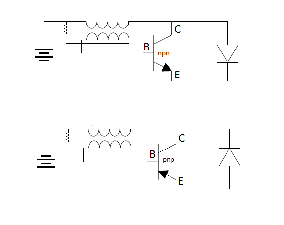
    The spark gaps will stop the coil from drawing from the power supply and ionize the dielectric ambient, it also allows only one polarity to hit the coil.

    I started a big project at work so havent had much time here lately but still working it out.
    Half of the Answer is knowing the right Question

    Comment


    • Yeah me too

      Work work work just got in.

      Sounds good for the definition Dave great diagram. Does this mean that sound of these circuits you post are actually put on a bread board?

      Or are the dozens of circuits you post still in the planning stages of theoretically analysis?

      I don't mean to sound critical here Dave but I have asked about which circuits have ever been tested and which ones are guess work. I understand that any circuit can be generated from software but finding one that doesn't burn out parts and works takes real hands on.

      I think many people see your circuit generator as a sort of gaming generator where it becomes addictive to see what the software can kick out next time.

      Is that how it is? I hope you do not find these questions offensive.

      In other words, people who might otherwise actually build one you your many circuits can't because they don't know which one is a real circuit and which of them are hypothetical.

      See what I mean?

      I love circuit generating, because without that art we would be stuck drawing out everything on paper to scan it in like the old days.

      Mike

      Comment


      • No offense Mike
        The circuits have not been tested, still in the planning stage.
        Not sure what you mean by software, I draw them up in ms paint and study them, I will build and test when I have the gates figured out.

        I knew we had to collect neg as well as pos and am developing a circuit to do just that, but yes its still in the planning stage.

        It has to be rational and simple, action reaction.

        It also has to ring true if you know what i mean, sometimes you just know.

        I dont expect anyone to build my idea's I just put them out there for consideration, I will build them in time.

        We have to be honest with ourselves, if you developed a circuit that put out more than it took to run it would you post it? probably not, not because of greed but because it would be very dangerous.

        Study every circuit you can find but follow your own path, just building everyone's nonworking circuits will get us nowhere.
        Half of the Answer is knowing the right Question

        Comment


        • Dot Dot Dash

          Originally posted by Dave45 View Post
          No offense Mike

          I dont expect anyone to build my idea's ...................

          We have to be honest with ourselves, if you developed a circuit that put out more than it took to run it would you post it? probably not, not because of greed but because it would be very dangerous.

          Study every circuit you can find but follow your own path, just building everyone's nonworking circuits will get us nowhere.
          Hi Dave that is a milestone essay

          I am glad to hear from you on this level of communication because a lot of experimenters feel the same way.

          In other words hat I am seeing is a sort of dot dot dash type of exchange on the web where they don't mind shooting of a few emails without pictures of their projects or putting out some photo's without explanation. As long it is an incomplete entry they feel safer.

          I see that and I wonder why but I think you have summed it up.

          If I get an overunity circuit going I will post it and we can go from there.

          Thanks for being honest.

          Mike
          Last edited by BroMikey; 09-10-2014, 06:06 PM.

          Comment


          • Beautiful Circuit

            Nice
            Персональный сайт - JOULE THIEF
            Half of the Answer is knowing the right Question

            Comment


            • Plus and Minus Boost Converters


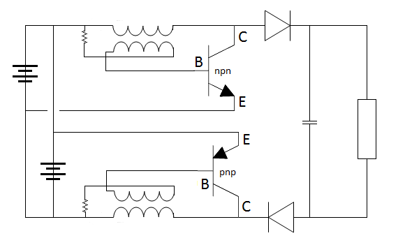
              Twin boost converters with bases firing from diodes.

              Double duty twin booster converter? I think

              Mike

              Comment


              • Twin Boost

                Hi mike, yes a nice little circuit to play with...basically a bistable oscillator principle. frequency dependent on the inductance in the main. Be careful within the RF regions though!!! as this could possibly pump out some interference.
                Regards Dupe.

                Comment


                • Pos and Neg boost converters

                  Originally posted by BroMikey View Post
                  Twin boost converters with bases firing from diodes.

                  Double duty twin booster converter? I think

                  Mike
                  Yep, looks like the coils are wound bifilar.
                  If you think about it pos in one winding neg in the other the bifilar coil is a capacitor of sorts.
                  Half of the Answer is knowing the right Question

                  Comment


                  • Of Sorts?

                    Originally posted by Dave45 View Post
                    Yep, looks like the coils are wound bifilar.
                    If you think about it pos in one winding neg in the other the bifilar coil is a capacitor of sorts.

                    Yeah the dot is on the top on one coil and the dot is on the bottom of the other.
                    That is the cap bank that the circuit is filling.

                    Mike
                    Last edited by BroMikey; 09-17-2014, 02:19 AM.

                    Comment


                    • Half of the Answer is knowing the right Question

                      Comment


                      • Mike you may have already seen this but thought I would bring it to your attention, Allen posted a vid here you may find interesting http://www.energeticforum.com/renewa...tput-coil.html

                        https://www.youtube.com/watch?v=Lczz...lWkKQ&index=85

                        You could probably do the same thing with your cap dump circuit, a piggy back coil to charge the source battery.

                        Anyway all the best, Im still working on the original pos neg circuit when I have time, will post when I get it working.


                        dave
                        Half of the Answer is knowing the right Question

                        Comment


                        • Just to let you know Im not all talk
                          https://www.youtube.com/watch?v=D58-...ature=youtu.be
                          Last edited by Dave45; 10-05-2014, 01:16 PM.
                          Half of the Answer is knowing the right Question

                          Comment


                          • Cap Dump Circuit

                            I use an identical circuit for one of my battery pulse chargers. The transistor is a BU208 TV line scan output. I junked several heavy duty commercial battery charger boards fitted with very large copper wound inductors on ferrite air cores. A few turns added around the existing windings provided the feedback.

                            Comment


                            • Hey Dupe
                              Which circuit are you referring too.
                              Half of the Answer is knowing the right Question

                              Comment


                              • This will be the next test, wound a core for it today.
                                Im slow but will get it done soon.

                                Half of the Answer is knowing the right Question

                                Comment

                                Working...
                                X