Announcement

Collapse
No announcement yet.

Cap Dump Circuit

Collapse
X
 
  • Filter
  • Time
  • Show
Clear All
new posts

  • Sheet Just got Real, HUH? (A Mr Clean Quote)

    Originally posted by Dave45 View Post
    This will be the next test, wound a core for it today.
    Im slow but will get it done soon.

    Looks like more than paper shuffling to me. Way to go Dave. Keep running those open end coils so I can find out what they do.

    I watched the video. Hypothetically just went orbital into the ionosphere

    I watched a few do some of these JT circuits and doubles but you are able to exceed the some of them all.

    Can't wait till your next release comes.

    Mike
    Comment


    • Last edited by Dave45; 10-06-2014, 11:56 AM.
      Half of the Answer is knowing the right Question

      Comment


      • Camp Dump circuit

        Originally posted by Dave45 View Post
        Hey Dupe
        Which circuit are you referring too.
        Hi Dave
        the npn circuit in #342 diode anode to collector, cathode to battery + and battery - connected positive of source.

        Comment


        • Hey Dupe
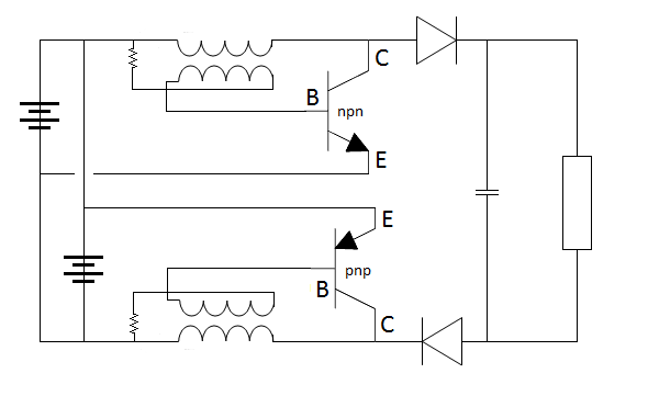
          Yea thats the circuit Bedini made popular, we can take it a step further.
          Its so simple it has been overlooked
          We tend to overcomplicate, our mind tells us it just cant be that simple.
          Separate the pos and neg and boost both.
          All the best
          dave
          Last edited by Dave45; 10-08-2014, 12:23 AM.
          Half of the Answer is knowing the right Question

          Comment


          • Originally posted by Dave45 View Post
            Hey Dupe
            Yea thats the circuit Bedini made popular, we can take it a step further.
            Its so simple it has been overlooked
            We tend to overcomplicated, our mind tells us it just cant be that simple.
            Separate the pos and neg and boost both.
            All the best
            dave
            What transistors are you planning on using Dave? The NPN types are plenty full but I'm not sure about PNP HV types! If the popular 2N3055 is chosen then 2N2955 is it's complementary.
            The other query I have is with the configuration, should ideally operate in push pull so to speak, but there's no synchronism between the two stages to switch the bases alternatively, only the outputs are paired.
            Certainly worth investigating though.

            Comment


            • Hi Dupe
              Yes there is no synchronization between the two stages but there really doesnt have to be since each is charging the opposite side of the cap.
              Iv thought alot on this myself, but just for testing I think it will do, maybe later we could work on synchronizing the two.

              Strange you brought up the 2n3055 and the 2n2955 thats what I ordered, they came in a few days ago.

              I still havent got my wire so Im going to wire up the small joule thief circuits and see what I can get from a 1.5 battery just out of curiosity.
              Half of the Answer is knowing the right Question

              Comment


              • Ok guys here it is
                I hooked the two circuits together using only one AA battery I also did not put the cap in just hooked the outputs to each side of a one watt led.
                This circuit works great the led will blind you, Im still seeing spots.


                Half of the Answer is knowing the right Question

                Comment


                • Sweet Double Jewel

                  Sure is bright


                  How many miliamps do ya figure?

                  You weren't kiddin when you said you were ready to rumble

                  Those Leds are rated at 20 ma I think right?

                  Happy experimenting. Great machine.

                  Mike

                  Originally posted by Dave45 View Post
                  Ok guys here it is
                  [/IMG]

                  Comment


                  • Hey Mike
                    Not sure about the miliamps I havent really taken any measurements yet.
                    This is a strange little circuit, Im still playing with it.
                    I dont think its ou but is strange
                    Im going to keep playing with it
                    I'll keep ya posted

                    dave

                    I need to try a different load, it ruined one of my leds
                    crazy
                    Half of the Answer is knowing the right Question

                    Comment


                    • I may need to synchronize the gates.
                      I know the stages are not running at the same frequency, they cant be the core windings arent the same.
                      Is it working in push pull mode, lots of questions.
                      The second stage does increase the brightness of the led
                      got me scratching my head
                      got to get to work I'll play with it tonight.
                      Half of the Answer is knowing the right Question

                      Comment


                      • Im late for work

                        Iv been watching Dave and Matt's 3BGS progress so I put three AA battery's in series turned the middle one around and am lighting the led's pos to pos or neg to neg.

                        got to get to work
                        later
                        dave
                        Half of the Answer is knowing the right Question

                        Comment


                        • Unknown Amp Draw

                          Okay since the amp draw is unknown let me tell you that when i do these Jt circuits using a 1Volt battery it can draw 100-200ma and in your case times 2 because it is a double whamee.

                          This is a minimum 3.5vdc 60 ma output

                          Or a Maximum 3.5vdc 120ma.

                          This should power 20 LED's

                          I have done the Lasersaber and JT circuits many times and know this from experience to be pretty close.

                          Now go to work adding bulbs. You could probably split a whole string of Xmas LED's into 3 or 4 sets to play with how much.

                          The little amp meters off ebay are 0-5 amp 0-1 amp 0-10 amps all $5 to the door.


                          Mike


                          Originally posted by Dave45 View Post
                          Hey Mike
                          Not sure about the miliamps I havent really taken any measurements yet.
                          This is a strange little circuit, Im still playing with it.
                          I dont think its ou but is strange
                          Im going to keep playing with it
                          I'll keep ya posted

                          dave

                          I need to try a different load, it ruined one of my leds
                          crazy

                          Comment


                          • Hey Mike
                            Im drawing 210 milliamps running four one watt led's.
                            The led's are not at full brightness.

                            I ran this setup all day and most of the night trying to kill the 1.5v battery it dropped out at .55v
                            Im charging the battery now between the collectors of each stage and still running an led across the collector and emitter of each stage.

                            Just playing with it, I plan on taking it to the next stage soon.
                            I have to buy more wire.

                            The pnp stage runs the led alot brighter than the npn stage.
                            Half of the Answer is knowing the right Question

                            Comment


                            • Best Cap dump for the 8 wire, 7 transistor Bedini Ssg?

                              Hey guys
                              So I read through this thread and maybe I missed it but I'm trying to find the closest circuit to Bedini's comparator 😬 does anyone have one?? I would be so very very appreciative and excited and glad lol

                              Trying to discharge 24v into 12v batt 😐I'm not into the 24 or 48 levels yet. I want to get this going and run tests then mayb graduate on up to higher voltage banks. I started this around a year ago and I don't have an oscilloscope yet but I've seen results of the spikes and have been working on the discharge circuit for a few months. I'm about to hook a generator coil up too and I want to maximize on that with a good cap dump circuit. This is my first attempt to reach out so please go easy on this newb. Thanks!!

                              Btw I been looking at you guyses posts off and on for months and almost feel like I know you, bro Mikey, Mario and farmhand lol

                              Comment


                              • Dump Circuits

                                Originally posted by Ben.hamilton83@gmail.com View Post
                                Hey guys
                                So I read through this thread and maybe I missed it but I'm trying to find the closest circuit to Bedini's comparator 😬 does anyone have one??
                                First I think it important to understand that cap dump circuits come in many forms. John Bedini has built about every circuit.

                                A comparator circuit is one, a timing cap dump circuit is another.

                                For each case 28-30vdc is released over a 12vdc battery.

                                Twice as much voltage as the battery being charged.

                                A comparator circuit waits to dump based on the voltage you set it at.

                                If you set it to 30vdc the circuit will wait till it fills the cap to 30vdc then dump. This is good for a varying input when charging the cap bank.

                                Like if a solar panel is being used to charge the caps, it will wait till the preset voltage is reached. If it is cloudy outside the caps may take 5-10 seconds to charge, then dump.

                                If you are using a timing circuit that discharges the cap 1-3 times per second then it becomes important that the input voltage be controlled or fixed.

                                Do you understand these basic statements?

                                The comparator is here somewhere. Do you actually require one? Or are you just curious?

                                It is funny you should bring this up because I was thinking today that I would like to locate a voltage shut down circuit as well as a safety precaution. Should the terminal slip off the SSSG generator HOOKED to the dump, at about 80volt my 21194's would go into smoke down mode. Not very funny.

                                This is why I am going to a MOSFET 460 that has a higher voltage capability.

                                I use a 555 timing circuit but the comparator circuit is equally as simple if you so desire or need it. John B has one for $600. Equivalently my dump circuit is valued at approx. $5000 minimum.

                                Some one will help us I am sure. I need a decent shut down circuit, say 50-60volts.

                                Here are few pictures from the start of the project that has been completed months ago. I can't find my final shots. I can run at 90 percent duty cycle all day long at 1500 watts in 100 degree heat. I used 12 fets and 4 balancing coils to low heat under these conditions. Max switching speed is 3-5 microseconds.

                                I currently discharge at 90vdc into a 36vdc bank of 1000ah or I can charge them in parallel and that would be approx 12vdc @ 3000ah.

                                I can dump a 60amp pulse at 90vdc all day long in 100 degree heat with no heat issues whatsoever. The sink is at 2-5 degrees above room temp MAX.

                                3 dumps per second I am a happy man with this unit

                                Thanks for popping in Ben

                                Mikey


                                Last edited by BroMikey; 02-13-2015, 08:07 AM.

                                Comment

                                Working...
                                X