Announcement

Collapse
No announcement yet.

Newman Motor Finally Explained?

Collapse
X
 
  • Filter
  • Time
  • Show
Clear All
new posts

  • Sourcing Free Magnet Wire

    Originally posted by gyula View Post
    Hi,

    Does this price US $ 90 per 1 lbs include shipping?

    Anyway, have you searched this wire at ebay? See some choices:
    https://www.ebay.com/sch/i.html?_odk...+10lb&_sacat=0

    here is a free shipping offer but only 7 lbs left (7 rolls by 1 lbs, that is):
    0.25 mm 30 AWG Gauge 460 gr ~1030 m (1 lb) Magnet Wire Coil Enameled Copper

    another (not free shipping but) cheaper than your above offer:
    ПÐ*ТВ-2: 0.25mm/ 30AWG Enameled Copper Magnet Wire 1.100kg/2.42Lbs.

    Good luck.

    Gyula
    I source my magnet wire from old-style TVs which I have been salvaging whenever I run across one.

    The quality is pretty good, and the cost is low.

    https://www.youtube.com/watch?v=7gk5Un1b7rs

    I'm looking to build something like in this video, but with the armature going along the length of the coil. Also, I will be using a Newman commutator.

    https://www.youtube.com/watch?v=T5RtBVvOviA

    I like the orientation that he has with this motor, but instead on one coil, I would have two, that is, one above and one below the armature. Also, I would be using a high impedance coil or high voltage coil of a microwave oven. Again, I would be using a Newman commutator.

    https://www.youtube.com/watch?v=pUDnPQY6yJI
    Last edited by vidbid; 08-27-2017, 05:28 AM.
    Regards,

    VIDBID

    Comment


    • Reed switch vs commutator

      Originally posted by vidbid View Post
      I source my magnet wire from old-style TVs which I have been salvaging whenever I run across one.

      The quality is pretty good, and the cost is low.

      https://www.youtube.com/watch?v=7gk5Un1b7rs

      I'm looking to build something like in this video, but with the armature going along the length of the coil. Also, I will be using a Newman commutator.

      https://www.youtube.com/watch?v=T5RtBVvOviA

      I like the orientation that he has with this motor, but instead on one coil, I would have two, that is, one above and one below the armature. Also, I would be using a high impedance coil or high voltage coil of a microwave oven. Again, I would be using a Newman commutator.

      https://www.youtube.com/watch?v=pUDnPQY6yJI
      Vidbid,
      Good vids. I've salvaged wire this way also. Used it on my first upright Newman motor.

      Tried the reed switches on the first build. But they would burn up or stick from all the bemf or usage.

      I rewound the aforementioned yesterday with trifilar wire from 3" x 4" coil I think is 24 to 26 awg. My caliper has dead battery will clarify later.
      So added salvaged TV wire to the trifilar and got good amount of wire.
      18 parallel 24 to 26 awg wires
      92 feet long
      .02 ohmic reading
      Wrapped top and bottom of a 4" pvc pipe union from Lowes. Pre-wrap drilled holes for zip ties to hold upper and lower coils in place.

      Have (4) ring or donut magnets on 5/8"(?) dowel on 1/4" threaded rod as axial through center of the union.

      All parts and such come from Lowes or salvaging, except the trifilar coil from earlier test of Bedini SSG.

      Just need to test different wiring schemes - parallel , parallel series connected, or like Turion stated a combo of both. If this small amount of wire will produce that elusive "Newman effect" ?

      Will post pics later,
      wantomake

      Comment


      • Pictures

        To All,
        Here are the pictures of the upright so far.

        [ATTACH]19857[/ATTACH] [ATTACH]19858[/ATTACH]

        Got some pvc assortment to build the commutator with.

        Can't do very good testing until comm is in place.

        wantomake
        Last edited by wantomake; 08-27-2017, 09:18 PM.

        Comment


        • Originally posted by wantomake View Post
          To All,

          Can't do very good testing until comm is in place.
          It really is incredible to see all the voltage a very long long wire
          can make for such a teeny tiny amount of input. The window motor
          and the Solid state Bedini oscillator.

          In fact every time I see this I see the window motor, it is the same
          thing. Built it and use it's pumping action in high efficiency oscillation.

          It is a great learning tool, build two or three and each time you do you
          will see that the shorter the wire the greater the output with a larger
          input while the longer wire (like 3x) will give way higher efficiency
          figures for input/output.

          In the end the goal is to somehow balance the load to input so when the
          pulses occur both input and output are sustained by the pumping action.

          Once this happens you will never be the same again. It is so delicate a
          process to find that single point or node, making this approach of course
          impractical. The point is that you will have something to go by for your
          next build and the one after that so each time an improvement can
          be witnessed.

          Only the experimenter who spends time with his hands and money knows
          what he has and if things are getting better. Thousands have started
          with this window motor type build. The commutator pulses and this is
          no new function, Tesla has the patents on this stuff while Joe was still
          setting on the fence.

          I have some really really long wire coils that are all twisted up and some
          not twisted and it is breath taking to see how little input it takes to get
          power out in high voltages. A solar panel to an oscillator pump could
          charge a huge bank of batteries.

          The purpose is to get free mechanical energy like to pump water otherwise
          put a rotor on it and build a lenz free generator.


          Last edited by BroMikey; 08-28-2017, 12:17 AM.

          Comment


          • Here is Paul Bab. board talk poster. I think 2012?

            Comment


            • Progress

              Bromikey,
              Very true the more builds the better picture and understanding of the process. I'm a hands on learning kind of person.

              This pvc type commutator is a pain in the arse. If anyone has a solid easier way that doesn't involve a cnc machine or paying some company to build one, please help out here.

              Really like those roller type brushes on those videos. UFOPOLITICS had the best ones I've seen. I'll be using long strips of brass or copper attached to stationary terminal blocks for commutator brushes.

              wantomake

              Comment


              • Larger is better

                Dave,
                Thanks for the input it helps. The size I'm using is 1 1/4" diameter with end plugs not caps. Hard to find any fabricating shops here in these small towns. So I try the copper sheeting cut into strips.

                Next larger machine will need much larger comm for sure.

                I always follow your builds. Especially your winding series, parallel etc.

                Much respect,
                wantomake

                Comment


                • The Newman Commutator

                  Originally posted by wantomake View Post
                  Vidbid,
                  Good vids.
                  Thanks. Much appreciated.

                  Originally posted by wantomake View Post
                  Tried the reed switches on the first build. But they would burn up or stick from all the bemf or usage.
                  wantomake,

                  Good points and interesting.

                  I want to say about the idea of using reed switches. Personally, I don't believe it's a Newman motor if it's using reed switches.

                  About the BEMF or CEMF, to me, that's the gold in the machine.

                  To me, the magic happens in the commutator. If you look at Newman's latest videos, take some time and study his commutator.


                  It looks like Newman has a "continuous" shorted band on his commutator, which I'll be implementing in my commutator design.

                  For the purposes of constructing a Newman commutator, I have a couple of steel discs that I'm playing with, but I'm thinking about using copper, instead, but I might just use one of the steel discs to prototype with.

                  I think the majority of people miss the importance of Newman's commutator in the design, and I'm not talking about his book. I believe people need to really watch his last few videos of his motor Big Eureka.

                  It's really a shame that he didn't explain its workings while he was alive.

                  Luckily, I think there's enough video segments of its operation that we can piece its construction together.

                  I believe the most important component in his motor is the commutator, especially, the commutator in Big Eureka.

                  I believe that's where our attention needs to be.
                  Last edited by vidbid; 02-15-2019, 01:06 PM.
                  Regards,

                  VIDBID

                  Comment


                  • Originally posted by BroMikey View Post


                    A solar panel to an oscillator pump could charge a huge bank of batteries.

                    Exactly that is what I'm looking for.
                    I have a very small PV system of about 250 Wp on the roof of my house, output regulated 24V DC, and want to use this small system to power appliances in my house. The aim is to have at least one airconditioning running. So what I have is only 4-5 hours daily sun which translates into 4-5 times 250 Wp which equals to 1-1.25 kWh per day, stored into two Trojan 12V lead-acid batteries in series.
                    The idea is to apply these explained principles of voltage pressure through DC pulsing, mix a big electromagnet in it like the Newman motor, and get out a lot of output (in the order of 10-15 kWh per day).
                    Which means I'll have to get at least a COP of 10, but I'm sure that while adding more wire and use stronger magnets, it should be doable.
                    My thinking used to be current based but now it is voltage based. After having read about so many inventions of so many inventors they all boil down to distort the aether in some smart way, and harvest the extra energy added by the same aether trying to compensate the distortion. Energy is abundant and magnetism (which is just an expression of the aether being distorted) is here to help us get the energy we need in a non-polluting way.
                    We just have to take care that Lenz law is circumvented when extracting all that atom power current on a secondary coil. The more magnet and copper wire weight on the main system, the more amplification we get on the secondary.

                    Thanks for all the updates, very good to see some progress is being made.
                    Will keep you guys updated too.

                    pjotterkjen

                    Comment


                    • Magnetism and electricity related to aether and energy

                      Originally posted by BroMikey View Post
                      Here is Paul Bab. board talk poster.
                      Yeah, I'm a big fan of Paul Babcock.
                      His first three presentations were a big eye-opener for me.
                      He has a great way to explain the basic principles of how magnetism and electricity work and how they interact with matter.
                      He says in his first video that his 'eye-opener' was the book of Joseph Newman... so that's why I read the first 9 chapters a couple of times with much attention.
                      And that is what I recommend everybody do first: read these chapters very thoroughly and let go of any pre-learned stuff.
                      After that, any prototype that applies the basic requirements should have no problem to get to work with the correct fine-tuning.

                      pjotterkjen

                      Comment


                      • Commutator

                        Originally posted by vidbid View Post
                        Thanks. Much appreciated.


                        wantomake,

                        Good points and interesting.

                        I want to say about the idea of using reed switches. Personally, I don't believe it's a Newman motor if it's using reed switches.

                        About the BEMF or CEMF, to me, that's the gold in the machine.

                        To me, the magic happens in the commutator. If you look at Newman's latest videos, take some time and study his commutator.


                        It looks like Newman has a "continuous" shorted band on his commutator, which I'll be implementing in my commutator design.

                        For the purposes of constructing a Newman commutator, I have a couple of steel discs that I'm playing with, but I'm thinking about using copper, instead, but I might just use one of the steel discs to prototype with.

                        I think the majority of people miss the importance of Newman's commutator in the design, and I'm not talking about his book. I believe people need to really watch his last few videos of his motor Big Eureka.

                        It's really a shame that he didn't explain its workings while he was alive.

                        Luckily, I think there's enough video segments of its operation that we can piece its construction together.

                        I believe the most important component in his motor is the commutator, especially, the commutator in Big Eureka.

                        I believe that's where our attention needs to be.
                        Vidbid,
                        You are right about the comm. So I will build one barrel and one wheel or disc type each. Also a single or two coil setup is possible.

                        First I'll try the barrel type comm, then build the disc shaped one to test with single coil setup.

                        Question- the blanks at 9:00 and 3:00 are those just the "blank spots" of the disk? I see the circular "short out". And the "firing" segments.

                        I agree, would be great if Newman had filled in some blanks(pun intented) about this comm design.

                        Why the continuous short? Does a large mass of wire hold magnetism or energy even while shorted? How will you harvest the CEMF or BEMF, the gold of the machine? Also what was the purpose for the giant capacitor?

                        The main reason I replicate this device is to answer the above stated. I've not tested this machine yet and confusion has already blocked my thinking........

                        I will go back and review the vids more.

                        wantomake

                        Comment


                        • Newman Motor Commutator

                          Missing image in previous post:


                          -----------------------------------

                          Originally posted by wantomake View Post
                          Vidbid,
                          You are right about the comm. So I will build one barrel and one wheel or disc type each. Also a single or two coil setup is possible.

                          First I'll try the barrel type comm, then build the disc shaped one to test with single coil setup.

                          Question- the blanks at 9:00 and 3:00 are those just the "blank spots" of the disk? I see the circular "short out". And the "firing" segments.

                          I agree, would be great if Newman had filled in some blanks(pun intented) about this comm design.

                          Why the continuous short? Does a large mass of wire hold magnetism or energy even while shorted? How will you harvest the CEMF or BEMF, the gold of the machine? Also what was the purpose for the giant capacitor?

                          The main reason I replicate this device is to answer the above stated. I've not tested this machine yet and confusion has already blocked my thinking........

                          I will go back and review the vids more.

                          wantomake


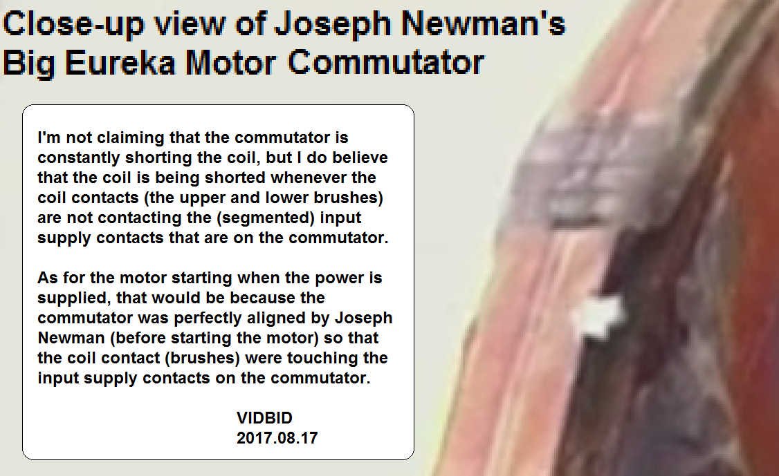
                          Newman Motor Commutator Contact on Large Disc Circumference


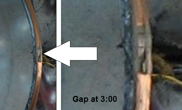
                          Newman Motor Commutator3 O'clock Gap on Large Disc Circumference


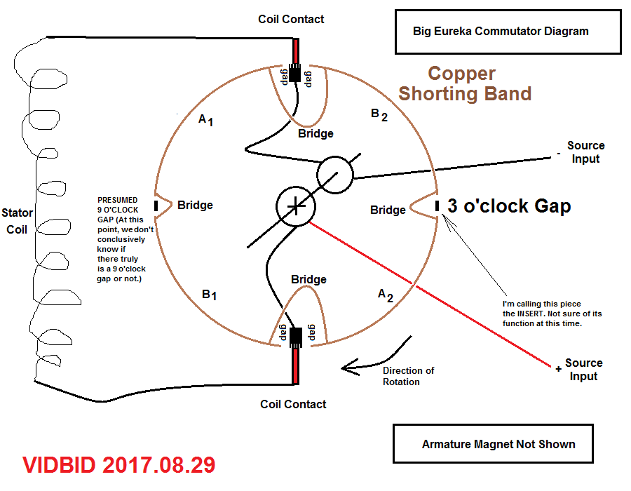
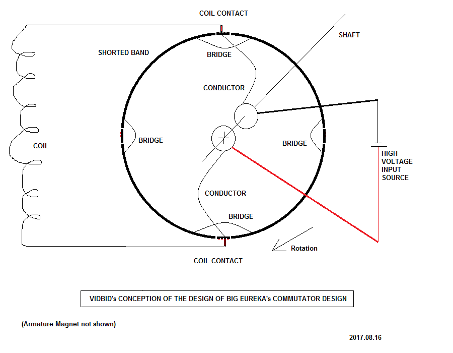
                          Possible Schematic or Diagram for Newman Motor Commutator

                          @wantomake, Thanks.

                          Let me start out by saying, to me, the first thing of importance is to make the observation.

                          That's what I do. I observe, and then I try to make an observation.

                          After I make the observation, then I will attempt to formulate a theory.

                          I'm not sure what the function of the 3 O'clock Gap is, but I do observe that there is clearly a 3 O'clock Gap there.

                          As for the 9 O'clock Gap, I'm only speculating that it exists. I don't know for certain that it is there, but I can speculate that if it is there, what then how it might affect the operation of the commutator.

                          As for the bridges across the commutator contacts, again, that is only speculation. At this point, I can only speculate.

                          I'm pretty sure that Newman was feeding the fly-back from his coil into his battery at some point. I believe (but I can't prove) that the function of the caps is to catch the fly-back in some way and hold it, possibly, as a buffer.

                          In one of his videos (I'm not sure which), Newman stated something about keeping the magnetic field in the coil (at least, that's what I believe that I heard.) Would his latest commutator design accomplish that? I believe the answer is Possibly.

                          Good luck to all who attempt any kind of replication based on Newman's latest work.

                          At this point, I believe Newman's latest motor works and produces overunity. I believe that the answer has got to be simple. I'm not worried about the Einsteinian theory that Newman embraced and tried to explain. He would have done better just to show how he built the machine, but he didn't with his latest machine.

                          So we have to piece it together with his videos and images of his latest machine.
                          Last edited by vidbid; 02-15-2019, 05:49 AM.
                          Regards,

                          VIDBID

                          Comment


                          • Newman commutator.

                            The major drawback to Newman's commutator, as I see it, is that it's connected directly to the spinning magnet axle.

                            This limit's the motor to one speed regulated by voltage alone. Separating the commutator from the spinner, as I separated Art porter's on the "Magnet Torque Amplifier" thread would allow the motor to operate over a wider range of R.P.M. and increase the availability of resonant sweet spots.

                            Comment


                            • V/RS Correlation

                              Originally posted by Allen Burgess View Post
                              The major drawback to Newman's commutator, as I see it, is that it's connected directly to the spinning magnet axle.

                              This limit's the motor to one speed regulated by voltage alone. Separating the commutator from the spinner, as I separated Art porter's on the "Magnet Torque Amplifier" thread would allow the motor to operate over a wider range of R.P.M. and increase the availability of resonant sweet spots.
                              Interesting perspective, though, I'm not sure how a voltage-to-rotational-speed correlation would be a drawback.

                              To increase rotational speed, increase voltage.


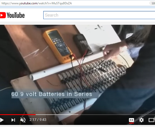
                              If 60 9-volt batteries gives you X RPM, and if 70 9-volt batteries gives you >X RPM, I'm not sure how that would be a drawback.

                              Couldn't you just dial in whatever rotational speed you wanted simply by adjusting a variac (which is ahead of a FWBR)?

                              As for separation, wouldn't disassociating the armature's magnet rotational function from the function provided by the commutator cause a possible phase misalignment between the function of the commutator and the relative position of the armature's magnet?

                              I'm not saying what you propose can't be done. In fact, it has already been done by Geoffry S. Miller.


                              (Later note: The above commutator is missing the coil shorting segments.)


                              (For what is a variac, see https://www.youtube.com/watch?v=kfETCn09hhc
                              Last edited by vidbid; 02-15-2019, 05:53 AM.
                              Regards,

                              VIDBID

                              Comment


                              • Originally posted by maxc View Post
                                My commutator. So far it will go .028 amp negative back too battery. Was using .03 aluminum mig wire as brushes. Needs more work.
                                With this commutator I can short the coil out but I noticed that pulls 20 more percent power and slows it down. I order 10 more pounds of wire and I have some high frequency transformer laminates. I'm going to remove the magnet rotor and use a laminate rotor. To beat lenz's law. Also I'm going to put the laminates in the coils.
                                Attached Files
                                Last edited by maxc; 08-29-2017, 08:52 PM. Reason: added pic

                                Comment

                                Working...
                                X