Announcement

Collapse
No announcement yet.

Newman Motor Finally Explained?

Collapse
X
 
  • Filter
  • Time
  • Show
Clear All
new posts

  • Originally posted by pjotterkjen View Post
    Yes, it sure is!
    In my understanding from what is written in the book, the BLANK allows no current to COMPLETE the circuit and thus prevents the current to go back to the input voltage source (all those tiny batteries in series). This prevents the batteries from draining quickly. So, only high voltage pressure is used, and a very short input current as a consequence (but only into the coil). This causes a magnetic field to build quickly, and in the BLANK segment, this field collapses which causes a current TRYING to flow to keep the magnetic field at the same strength. This in turn turns the magnet with a higher force WITHOUT using (draining) the battery.
    Then the SHORT segment is there to EXTEND the current flowing, and this lets the magnet rotor turn with an even greater force. Batteries gets part of the BEMF through the commutator and are charged that way.
    Timing of these segments is extremely important and Newman says each build has his own tuning or exact timing of these segments with respect to the position of the magnet rotor.

    Then the Eureka communtator. This one keeps me puzzling. How did Newman go from the multi segment commutator to the big one with only four copper segments? And, were they interconnected as you think they are?
    Geoffrey talks a little bit about it in his presentation. It starts at 51:38. Can anybody tell me what it means when he says "you put a 45 here and a 45 here (on the other side)"? Is he referring to the position of the brushes? Because the small commutator is covered with a complete ring of copper.
    Then he says: "you go from 12 to 3 o'clock with a copper strip, and from 6 to 9 o'clock with another strip of copper. Then you connect the small copper ring on the front to one of the strips, and the small copper ring on the back gets connected to the other copper strip. And that's it."
    So vidbid, you may want to listen to this, and I guess you will make some adjustments in your design accordingly.
    Q: were the other segments (assuming there were four) connected to something? Interesting question. Geoffrey does not answer that one, so maybe he can here? Were they maybe used to flip the voltage polarity, as in the older commutator with the many segments?
    Anyways, to my understanding, if Geoffrey is telling the truth, you need to remove the bridges, and connect either A1-A2 or B1-B2 to the small copper rings, as indicated by Geoffrey in the video.
    This would allow for me to understand how the big machine can start on it's own. Connecting the voltage in the position where the voltage is applied to the coil would generate the magnetic field, hence a big torque on the magnet rotor through the interaction of the coils's electromagnetic field with the magnetic field of the magnets.
    Of course, you will need to add in the big capacitors in your design to suppress the BEMF spike. Seems important to me.

    Geoffrey further states in his presentation (a bit before the above mentioned description of the big commutator) that any build that presents an electronic way of pulsing cannot be a Newman motor. He says you need the commutator. I wonder if that is true and I'm planning to find out when I have the 15-C2 (Ch. 6 book) or 22-K1 (p. 67 book) on my bench and getting ready to replace the mechanical (moving) parts with an electronic version.
    That is going to be a wonderful journey. I think the combination of Bedini's electronic inventions and Newman inventions together with Babcock's switching technology could well produce an highly efficient small home unit that produces enough energy for daily use, without having to use huge amounts of pounds of wire or lots of PV panels on my roof.

    If only they could have gathered together, like the three musketeers, they would have had so much breakthrough power. So now, it's up to us, develop the thing and make it all open source so everybody can build one for his own use.

    Can't wait to get going.

    pjotterkjen
    The book is a good starting place, no doubt.

    I think a good finishing place is building a Newman motor based on Big Eureka, specifically, the Big Eureka commutator.

    There's only two rotating contacts, though, they are segmented. I think that there are about four segments per contact, but then there is the copper shorting band (so-termed by me,) and I see not mention of that in his book, and that would be because it came later, I believe.

    So, there's my two cents on it.

    Regards,

    VIDBID

    Comment


    • Deleted that post

      Originally posted by vidbid View Post
      Have you watched the Newman Movie that came out in 2016?
      Vidbid,
      I deleted that post you quoted. After watching the presentation again, it proves I was wrong to post that statement.

      What I saw the second (and some parts third or fourth) time the following:
      1. Eureka had a primary and secondary or motor and generator winding.
      2. 5 awg winding single winding and 38 awg multi-strand parallel winding on top of the first.
      3. Must be large quantity of magnet wire to get Newman Effect. Size and mass matters.
      4. Geoffrey says nothing at all about "shorting segments" on either type of commutator. Only that a segment from 12:00 to 3:00 connects to one battery pole. And another segment from 6:00 to 9:00 connects to the other battery pole.

      But everyone must come to own understanding of this machine. I'm building a much smaller size that I'm sure will not show the Newman Effect. But to understand how to build something usable this is good practice and insight for myself. I'll never afford a 7000 lb(forgot weight) unit like the Eureka, but want to build a motor/generator size unit eventually. Geoffrey mentioned this also. How to get massive amounts of wire(for Newman Effect) in smaller unit is going to be a challenge. Newman did put a motor size unit in his "red" car.

      Just my observations and thinking,
      wantomake

      Comment


      • GAP commutator.

        The DC fan, latching Reed switch commutator I just finished designing could run any of Joe's motors. It's much easier to relocate the trigger magnets on the tube then it would be to tailor a copper strip. Every individual Newman motor is unique and needs it's own personalized commutator timing arrangement.
        Last edited by Allen Burgess; 08-31-2017, 11:52 PM.

        Comment


        • Progress

          Vidbid,
          Still working on commutator. I picked up good tip from email friend on replication methods. To build parts so that changes can be made if possible. So my disc commutator can be changed to add shorting segments. The bad thing is I'll never get that Newman effect with this desktop size unit. So any tests results may not be helpful to anyone here.

          Hope to finish today with that part and move on to wiring the coil to complete the setup.

          wantomake

          Comment


          • Split positive

            Here's a split positive test:

            Newman's "Short" contact on his commutator feeds his source batteries the same way you see me charging batteries below: Aaron states that "It's the voltage differential between the positives", not the power to ground that completes this self charging circuit".

            My reverse charging effect neutralization pulse alternator works the same way. One contact short back to to source.

            Here's a link to the video: Just fast forward through the dead space:

            https://www.youtube.com/watch?v=NzQtyFp_Ghk
            Attached Files
            Last edited by Allen Burgess; 09-04-2017, 04:07 PM.

            Comment


            • Test will tell

              To All,
              Happy Labor Day to everyone.

              It will be that for myself. Very laborious to get this "desk top" size Newman Machine to a testing stage.

              Finished the commutator disc and now mounting on platform next to coil. It looks very "steam punkish" with the copper and white cutting board plastic. I built one barrel shaped and disc shaped so could see which is easier to build, use, and maintain. No not a production engineer, but think it wise to try both.

              Not sure yet the wiring/connecting of coil to get motoring and generator production without adding generator coils. Harvesting the "shorted" spikes may not help with this size coil. The coil is 18 strands in parallel. I will test different wiring schemes to see what the "test will tell".

              Hey look a delightful cup of coffee in front of me needing a warm up and sipping cause it's cool outside.

              wantomake
              Edit: The barrel commutator will be used with two coil scheme, while the disc comm will be used with single coil scheme. As per the Geoffrey Miller pdf. The flyback controlled by capacitors.
              Last edited by wantomake; 09-04-2017, 07:57 PM.

              Comment


              • Superposition; Two Loop Problem:

                http://www.energeticforum.com/redire...%2Fsuppos.html

                The power that travels back to the battery from my oscillator is summed algebraically; Therefore, we subtract the source power from the power that's generated in the electro-magnet from the regauging, and the remainder is the charge that replenishes the battery. No power ever reaches the coil from the battery after the first pulse. The second pulse is generated by the magnet coil itself, and the excess passed back to source.

                The same relationship applies to the "Newman Motor" commutator short.

                The Neutralization Pulse Oscillator is a "Newman Motor" short circuit hybrid. I have reached infinity with that simple a design! The Reverse Charging Effect video is posted above in comment #393.
                Last edited by Allen Burgess; 09-04-2017, 04:21 PM.

                Comment


                • Assembly

                  The assembly has gone ok. And did get to try a basic machine run.

                  The multi-strand coil wrap is hard to clean, connect and measure but can be done.

                  I only used 5 strands of wire to try a machine run. The disc works good. I used brass strips from Lowes as comm brushes. Some small sparks but believe more 9 volt batteries is needed. Don't own a variac so can't use ac then FWBR to dc power source. Like vidbid stated, want to be a purist and use battery power just as Newman did. Back to Lowes for more batts.

                  wantomake

                  Comment


                  • Newman Batteries.

                    Originally posted by wantomake View Post
                    The assembly has gone ok. And did get to try a basic machine run.

                    The multi-strand coil wrap is hard to clean, connect and measure but can be done.

                    I only used 5 strands of wire to try a machine run. The disc works good. I used brass strips from Lowes as comm brushes. Some small sparks but believe more 9 volt batteries is needed. Don't own a variac so can't use ac then FWBR to dc power source. Like vidbid stated, want to be a purist and use battery power just as Newman did. Back to Lowes for more batts.

                    wantomake
                    @wantomake,

                    Remember, Newman's batteries were deader than door nails. The voltage on my 12 volt was down to 8.52 when I performed my oscillator test.

                    The commutator short "Superposition" charging can't happen if the battery source is higher in power then the output from the coil.

                    Comment


                    • ????

                      Originally posted by Allen Burgess View Post
                      @wantomake,

                      Remember, Newman's batteries were deader than door nails. The voltage on my 12 volt was down to 8.52 when I performed my oscillator test.

                      The commutator short "Superposition" charging can't happen if the battery source is higher in power then the output from the coil.
                      AB,
                      Sorry I'm not familiar with "superposition" charging. Also I'm not using a "short" on my comms yet. As I've posted, this is only a basic machine build to help me to better understand the design and operation of this machine. I'm replicating solely from Geoffrey Miller presentation pdf.

                      As my knowledge base is low in electronics, electrical, and FE. I can build and still gain understanding in all the above. What I'd give for an engineering background. Like Popeye said, I yam what I yam.

                      Thanks anyway, I'll try to keep up,
                      wantomake

                      Comment


                      • Originally posted by wantomake View Post
                        AB,
                        Sorry I'm not familiar with "superposition" charging. Also I'm not using a "short" on my comms yet. As I've posted, this is only a basic machine build to help me to better understand the design and operation of this machine. I'm replicating solely from Geoffrey Miller presentation pdf.

                        As my knowledge base is low in electronics, electrical, and FE. I can build and still gain understanding in all the above. What I'd give for an engineering background. Like Popeye said, I yam what I yam.

                        Thanks anyway, I'll try to keep up,
                        wantomake
                        Superposition merely means higher charge level; Current always travels downhill from the higher charge source to the lower charge destination.
                        Last edited by Allen Burgess; 09-05-2017, 09:13 PM.

                        Comment


                        • Vidbid,
                          How is your build going? I know your commutator is including the "shorting" segment. Any results would be good to read.

                          Mine aren't encouraging so far. I wound my coil as two separate coils. Top and bottom of the pvc 4" union piece. I wanted to use one coil as motor and the other as generator. But no motoring yet. Using 17 9 volt batteries in series to power the machine. The timing is set. Good contacts on commutator. Only thing can figure is the coil needs to be re-wound.

                          wantomake

                          Comment


                          • Progress Report

                            Originally posted by wantomake View Post
                            Vidbid,
                            How is your build going? I know your commutator is including the "shorting" segment. Any results would be good to read.

                            Mine aren't encouraging so far. I wound my coil as two separate coils. Top and bottom of the pvc 4" union piece. I wanted to use one coil as motor and the other as generator. But no motoring yet. Using 17 9 volt batteries in series to power the machine. The timing is set. Good contacts on commutator. Only thing can figure is the coil needs to be re-wound.

                            wantomake
                            Hi wantomake,

                            Not too much to report.

                            I think that I'm going to use a flat copper disk as the commutator.

                            For example: 3" Dia x 1" Thick Copper Round Disk Disc Rod Bar Stock 99.9% Cu

                            3" Dia x 1" Thick Copper Round Disk Disc Rod Bar Stock 99.9% Cu | eBay

                            I could center-tap it. Then, slot out the places for the contacts with epoxy holding the contacts and also providing the non-conductive material for the spaces.

                            I'm still working on my design.

                            Coils will be provided by microwave oven transformer high voltage coils.

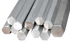
                            Not sure as to what to make the armature shaft out of. I was thinking fiberglass for its nonmagnetic properties; however, Newman said to use steel hex bar.


                            For the slip rings, I'm still considering my options. Maybe I can find some off an old motor.


                            For the magnets, maybe center-hole type Neodymium magnets could be attached to a hex bar shaft.


                            Anyhow, that's where I'm at.
                            Regards,

                            VIDBID

                            Comment


                            • Originally posted by vidbid View Post
                              The book is a good starting place, no doubt.

                              I think a good finishing place is building a Newman motor based on Big Eureka, specifically, the Big Eureka commutator.

                              There's only two rotating contacts, though, they are segmented. I think that there are about four segments per contact, but then there is the copper shorting band (so-termed by me,) and I see not mention of that in his book, and that would be because it came later, I believe.

                              So, there's my two cents on it.
                              vidbid,
                              You may want to review the presentation of Geoffrey.

                              Geoffrey states clearly that only 12-3 and 6-9 o'clock are interconnected with the small commutator rings, And that's all, he said. So, you may be right about the Big Eureka not having an internal commutator, but if Geoffrey is right (and I'll assume he is) then you need to adjust your drawing.
                              The two pairs of copper segments were connected through the bridges you draw, but not all four. Something like this: A1-A2 and B1-B2.

                              The voltage applied by the batteries when the rotor is in one of the FIRE segments will generate a big electromagnetic field which interacts with the magnetic field of the magnets on the rotor and create a torque, hence it starts turning.

                              So, we would have four FIRE segments and four BLANK segments.
                              The absence of SHORT segments is because Newman used capacitors that were helpful in suppressing the sparks. No need for complicated commutator design anymore. The capacitors are charged when the coil discharges its stored energy during the BLANK segments. Actually, the coil with the capacitors and the inductive reactance (or resistance when the rotor is not turning) represent a simple RLC circuit.

                              pjotterkjen
                              Last edited by pjotterkjen; 09-06-2017, 04:13 AM. Reason: correction

                              Comment


                              • Originally posted by pjotterkjen View Post
                                vidbid,
                                You may want to review the presentation of Geoffrey.

                                Geoffrey states clearly that only 12-3 and 6-9 o'clock are interconnected with the small commutator rings, And that's all, he said. So, you may be right about the Big Eureka not having an internal commutator, but if Geoffrey is right (and I'll assume he is) then you need to adjust your drawing.
                                The two pairs of copper segments were connected through the bridges you draw, but not all four. Something like this: A1-A2 and B1-B2.

                                The voltage applied by the batteries when the rotor is in one of the FIRE segments will generate a big electromagnetic field which interacts with the magnetic field of the magnets on the rotor and create a torque, hence it starts turning.

                                So, we would have four FIRE segments and four BLANK segments.
                                The absence of SHORT segments is because Newman used capacitors that were helpful in suppressing the sparks. No need for complicated commutator design anymore. The capacitors are charged when the coil discharges its stored energy during the BLANK segments. Actually, the coil with the capacitors and the inductive reactance (or resistance when the rotor is not turning) represent a simple RLC circuit.

                                pjotterkjen
                                I shall give your statements consideration.
                                Regards,

                                VIDBID

                                Comment

                                Working...
                                X