Announcement

Collapse
No announcement yet.

Newman Motor Finally Explained?

Collapse
X
 
  • Filter
  • Time
  • Show
Clear All
new posts

  • Originally posted by Kokomoj0 View Post
    Its difficult to comprehend why you are having so much trouble with such a simple circuit. I hope this helps.


    The battery is not in the circuit when it is running so adding a coil between the battery and the cap does nothing at all.

    The switch is placed to the left to charge the source cap, once the source cap is charged the switch is placed to the right for operation and as you can see the battery is completely removed from the circuit. I omitted the transistor switching circuit for less clutter.

    C1 is the source cap, D2 in series with the the output cap charges c2, D3 is just added for safety so you dont toast your transistor. I omitted D1 and put up the original drawing.

    The circuit you used for your test has the output cap in series with the transistor and charges it directly off the source. The circuit as shown above only allows pulses through from the coil to the output or load cap.

    If you want correct results you need to do your experiment again using the above circuit.

    Yes I have a closed mind because laws of physics are called laws because you cannot defeat them. If you or anyone else could we would be running our cars using your free energy devices long ago, and none of that changes the fact these guys are frauds.

    Again I dont want to discourage anyone from leaning about coils, but I can tell people out here that a little bit of school goes a long way, both in producing correct designs and understanding what is really going on and why you will never get OU from coils caps and magnets, unless they are set up to receive some outside source, like stifflers resonator.
    after having seen the circuit closer look, I realized it is not the circuit I built..
    your circuit is wrong.. I see no path for that cap to take the inductive discharge. rather than c-e of the transistor..
    perhaps it will work if you reverse the diode at the top..

    anyway Its out of topic and you probably would just state otherwise.. taking this into a senseless closed minded discussion.

    Comment


    • Originally posted by ricards View Post
      after having seen the circuit closer look, I realized it is not the circuit I built..
      your circuit is wrong.. I see no path for that cap to take the inductive discharge. rather than c-e of the transistor..
      perhaps it will work if you reverse the diode at the top..

      anyway Its out of topic and you probably would just state otherwise.. taking this into a senseless closed minded discussion.
      What continues to be incomprehensible to me is why you persist in forcing me to correct everything you say out here. I suppose the spice software is closed minded too? Are you serious or just trolling me?

      No its not the circuit you built, I told you several posts ago it is what you must do to correct the circuit you built because your circuit has errors. Your discharged output cap is in series with the 'source' which cannot be if you want to charge the output cap off the pulses from the coil.


      I used a manual switch in place of the transistor to make it easy because frankly you are wasting everyone time out here, but this hopefully will put this to rest. You can see the cap on the right charges just fine and dandy in the negative direction with the diode as drawn.

      Your continued mistake is to charge c2 direct off of c1 which is what will happen if you reverse the diode.

      Here is your circuit:


      The transistor is a switch:


      Below is the same thing as your circuit replacing the transistor with a switch, the reed and magnet is irrelevant and useless, all you need to do is turn your transistor on and leave it on to charge the cap, no pulses from the coil whatsoever just like in the spice I made to help you understand the problem.


      As you can see you are just dumping the voltage from one cap to the other. The voltage on the discharged cap goes immediately to max, all you had to do was turn on your transistor and leave it on, like a switch as I have shown above. Its directly charging one cap from another and all your coil is doing is adding a small delay to the charge time without any switching required.

      You dont need the coil at all, its just acting like a hunk of wire between the cap and switch or transistor. I suppose to be fair, in some respects learning what doesnt work is as important as learning what does
      Last edited by Kokomoj0; 05-13-2018, 10:07 AM.

      Comment


      • [/QUOTE][/QUOTE]
        Originally posted by ricards View Post
        after having seen the circuit closer look, I realized it is not the circuit I built..
        your circuit is wrong.. I see no path for that cap to take the inductive discharge. rather than c-e of the transistor..
        perhaps it will work if you reverse the diode at the top..

        anyway Its out of topic and you probably would just state otherwise.. taking this into a senseless closed minded discussion.
        Ricards,
        I recognized that closed minded non-buildering disruptor from the beginning. Only answer is the "ignore list" setting. Ahhh so peaceful and quiet.

        wantomake
        Last edited by wantomake; 05-13-2018, 12:35 PM.

        Comment


        • Originally posted by wantomake;

          Ricards,
          I recognized that closed minded non-buildering disruptor from the beginning. Only answer is the "ignore list" setting. Ahhh so peaceful and quiet.

          wantomake
          As much as you would like to pretend its my problem is yours. Hate to tell ya but you are living in the stone age.

          In fact I did 'build' the circuit in SPICE as you can see in the gifs I provided, you would be wise not to pretend otherwise.

          I built the circuit in a matter of maybe 5 minutes each, the time consuming part is preparing them to put up here to teach you guys whats going on.

          What Can You Do With SPICE?

          More specifically, it is a general-purpose circuit simulation program that provides linear AC analysis, non-linear transient analysis, and nonlinear DC analysis.

          Analysis is performed by solving combinations of theoretical and experimental (device model) equations representing the behavior of elements based on Kirkhoff's current and voltage laws, utilizing modified nodal point analysis.

          Device Model

          A device model is an analytical expression that was developed based on theoretical and experimental study.

          Elements and devices can be simulated:
          • Passive components (i.e. resistors, capacitors, inductors)
          • Active devices (e.g. diodes, bipolar transistors, MOSFETs)
          • Transmission lines
          • Power sources

          Analysis methods:
          • Transient
          • DC
          • Small-signal AC
          • Noise

          Until SPICE, IC design was carried out entirely by hand.
          What is SPICE? | Electronics Basics | ROHM
          Spice modeling is how we design circuits today instead of wasting time and resources by winding coils only to scrap them and find it all in the scrap yard when you guys give up because your hand wound coils do not work the way you dreamed.

          So unless you can show us some mysterious mojo schtick going on that no one in the history of electricity every thought of the SPICE analysis will give you the 'correct' answers for your design no wire required, things like stiffler is doing excepted since the program has no algorithm for spacial inductance that I am aware of. Newman, smith and stevens tpu have nothing to do with spacial inductance.

          The newman sparkler is a fraud, just like the tpu and that suit case guy dennis or don smith or whatever his name is. They prey on people who can not see through their scam.

          I even went so far in trying to help you as to give you the stiffler resonator youtube clip which has been proven to work by several replications, but its a lot more complicated and requires an excellent understanding of induction principles and what it takes to set the whole system into oscillation.

          So you see there are things that actually do work out here but it seems some people are prone to waste their time thinking they will be the one to make the impossible possible! It hasnt happened yet and it wont be happening anytime soon.

          You can thank ricards for taking it off topic with his so called 'simple circuit'.

          Personally I'd like to see people work on projects that are possible and can lead to success instead of failure. Whats important is to understand what is really going on with these devices not what one 'hopes' is going on. The frauds and their worshiping apologists are the disruptors not me.

          Another person to check out is the oldscientist on youtube, he does a good job on most of his experiments and has equipment to back it up and if you are into Tesla coils Meyl does the best job I have seen out here.
          Last edited by Kokomoj0; 05-13-2018, 07:19 PM.

          Comment


          • Originally posted by Kokomoj0 View Post
            As much as you would like to pretend its my problem is yours. Hate to tell ya but you are living in the stone age.

            In fact I did 'build' the circuit in SPICE as you can see in the gifs I provided, you would be wise not to pretend otherwise.

            I built the circuit in a matter of maybe 5 minutes each, the time consuming part is preparing them to put up here to teach you guys whats going on.

            Spice modeling is how we design circuits today instead of wasting time and resources by winding coils only to scrap them and find it all in the scrap yard when you guys give up because your hand wound coils do not work the way you dreamed.

            So unless you can show us some mysterious mojo schtick going on that no one in the history of electricity every thought of the SPICE analysis will give you the 'correct' answers for your design no wire required, things like stiffler is doing excepted since the program has no algorithm for spacial inductance that I am aware of. Newman, smith and stevens tpu have nothing to do with spacial inductance.

            The newman sparkler is a fraud, just like the tpu and that suit case guy dennis or don smith or whatever his name is. They prey on people who can not see through their scam.

            I even went so far in trying to help you as to give you the stiffler resonator youtube clip which has been proven to work by several replications, but its a lot more complicated and requires an excellent understanding of induction principles and what it takes to set the whole system into oscillation.

            So you see there are things that actually do work out here but it seems some people are prone to waste their time thinking they will be the one to make the impossible possible! It hasnt happened yet and it wont be happening anytime soon.

            You can thank ricards for taking it off topic with his so called 'simple circuit'.

            Personally I'd like to see people work on projects that are possible and can lead to success instead of failure. Whats important is to understand what is really going on with these devices not what one 'hopes' is going on. The frauds and their worshiping apologists are the disruptors not me.

            Another person to check out is the oldscientist on youtube, he does a good job on most of his experiments and has equipment to back it up and if you are into Tesla coils Meyl does the best job I have seen out here.
            All talk.. no work.. off topic.
            Its no fun if it's just the computer and your mind..
            Nothing wrong with SPICE..
            But something's wrong with you.
            Last edited by ricards; 05-13-2018, 11:41 PM.

            Comment


            • Yes: Peaceful and quiet

              wantomake[/QUOTE]

              Hello Wantomake,

              I also placed the disruptor on my IGNORE LIST !

              Also frees up more thread space for me.

              You have already seen the MONSTER COIL Pic's I sent you

              But now I am including them here for other members to view.

              All the NECESSARY restraints and hold down Zip Ties can be seen also.

              As I said to you I am now working on the commutator system to alternate the DC voltage through the Coil to keep The Magnet Rotor Spinning.

              Other Items needed will follow after.

              Hope, as you do , you are soon well and back on your 3BG Build.


              Respectfully,

              Clarence
              Attached Files
              Last edited by clarence; 05-14-2018, 06:33 PM.

              Comment


              • Power of the builders

                Ricards,
                I recognized that closed minded non-buildering disruptor from the beginning. Only answer is the "ignore list" setting. Ahhh so peaceful and quiet.

                wantomake[/QUOTE]

                Hello Wantomake,

                I also placed the disruptor on my IGNORE LIST !

                Also frees up more thread space for me.

                You have already seen the MONSTER COIL Pic's I sent you

                But now I am including them here for other members to view.

                All the NECESSARY restraints and hold down Zip Ties can be seen also.

                As I said to you I am now working on the commutator system to alternate the DC voltage through the Coil to keep The Magnet Rotor Spinning.

                Other Items needed will follow after.

                Hope, as you do , you are soon well and back on your 3BG Build.


                Respectfully,

                Clarence[/QUOTE]


                Clarence my ole' friend,

                Smart move on the "ignore list".

                I just will not waste time or space on such posters. The commutator is a good idea. Will you be "shorting" this coil or the top one? That's if you plan to build a top coil.

                Before this bug hit me, I was shorting the coil on the upright Turion generator. Just to see the fireworks display. Each pulse almost melted the HD reed switch. That's only 3 lbs. of magnet wire compared to your 10 lbs. I read some builders were shorting their coils more than once per passing of the magnet. Looks like J. Newman did also.

                Just some thoughts as I sit and recover.

                wantomake

                Comment


                • Originally posted by clarence View Post

                  I also placed the disruptor on my IGNORE LIST !

                  Also frees up more thread space for me.

                  You have already seen the MONSTER COIL Pic's I sent you

                  Clarence

                  Some of that stuff was found to be bot's Aaron chimed in about
                  how he cleaned out a bunch from last year. Maybe I should put
                  bots on my list, good idea.

                  In the mean time good to see yer still kickin over there and your
                  coil is Mega. Can't wait to see the huge double whammy magnet
                  blocks to go with that.

                  Somebody got to make this thing work and do away with the last
                  50 years of speculation. Waintin on ya.

                  Comment


                  • Good move

                    Originally posted by BroMikey View Post
                    Some of that stuff was found to be bot's Aaron chimed in about
                    how he cleaned out a bunch from last year. Maybe I should put
                    bots on my list, good idea.

                    In the mean time good to see yer still kickin over there and your
                    coil is Mega. Can't wait to see the huge double whammy magnet
                    blocks to go with that.

                    Somebody got to make this thing work and do away with the last
                    50 years of speculation. Waintin on ya.
                    Brodude,
                    Yes over on Small Experiments thread Admin warned him about the disrespect toward another member.

                    We All are here to build, learn, support these different builds. Sure there will be those that disagree. But don't be disruptive and negative. Show your work with explanation and in the "spirit" of FE exploration.

                    Can't wait to see what my ole' sippin friend turns out on his impressive build. We will know with experience and true testing IF indeed J. Newman was a con or genius. Judging from how big brother teamed up against him from the video, I'm thinking the latter.

                    Just my opinion.
                    As always time to nuke the coffee,
                    wantomake
                    Last edited by wantomake; 05-15-2018, 12:09 PM. Reason: Forgot coffee

                    Comment


                    • old video different name same concept.

                      Keppe Motor, actually was the first thing I've experimented with..

                      but It really is not that different to newman's so I think this still is on topic..

                      I've stumbled such video in the past.

                      this might be of some interest to you guys.

                      https://www.youtube.com/watch?v=xvN5gxhTi04

                      Comment


                      • bots

                        Originally posted by BroMikey View Post
                        Some of that stuff was found to be bot's Aaron chimed in about
                        how he cleaned out a bunch from last year. Maybe I should put
                        bots on my list, good idea.

                        In the mean time good to see yer still kickin over there and your
                        coil is Mega. Can't wait to see the huge double whammy magnet
                        blocks to go with that.

                        Somebody got to make this thing work and do away with the last
                        50 years of speculation. Waintin on ya.
                        Bots can sign up, but they can't post since 100% of every membership that gets approved is done manually. The bots will only be pending memberships and that's about it.
                        Sincerely,
                        Aaron Murakami

                        Books & Videos https://emediapress.com
                        Conference http://energyscienceconference.com
                        RPX & MWO http://vril.io

                        Comment


                        • Change in commutator system

                          Originally posted by wantomake View Post
                          Brodude,
                          Yes over on Small Experiments thread Admin warned him about the disrespect toward another member.

                          We All are here to build, learn, support these different builds. Sure there will be those that disagree. But don't be disruptive and negative. Show your work with explanation and in the "spirit" of FE exploration.

                          Can't wait to see what my ole' sippin friend turns out on his impressive build. We will know with experience and true testing IF indeed J. Newman was a con or genius. Judging from how big brother teamed up against him from the video, I'm thinking the latter.

                          Just my opinion.
                          As always time to nuke the coffee,
                          wantomake
                          Hello wantomake,


                          Since last word from me,
                          I found out that I DO need a DUAL Commutator system to ALTERNATE the DC
                          voltage through the coil.
                          The DUAL commutator will allow enough Fire time to off time through the coil
                          To get the job done.
                          Only problem is that another commutator and brush holder will have to be purchased .
                          At present my funds to do so are just not there. More will not be available until June 20 th.
                          Means a real long wait. So nothing will be coming from me during that time.

                          Just wanted to let you and members know.

                          Respectively,

                          Clarence
                          Attached Files

                          Comment


                          • Good uses

                            Clarence ole friend,
                            I understand about the funds. The SS doesn't go so far these days.

                            The second commutator will do the job timing the on,off, and shorting to the capacitor. From the picture you posted I built a short and smaller version. It was 2" pvc pipe with caps on ends that held it in place on threaded rod. Used 1/2" copper strips from old started coils. But as the picture shows more contact area keeps the sparking down to avoid heat and scarring of the contacts.

                            Look forward to your progress. We got big time monsoon season here so just trying to stay dry.

                            Later my friend,
                            wantomake

                            Comment


                            • Reposting Missing Image


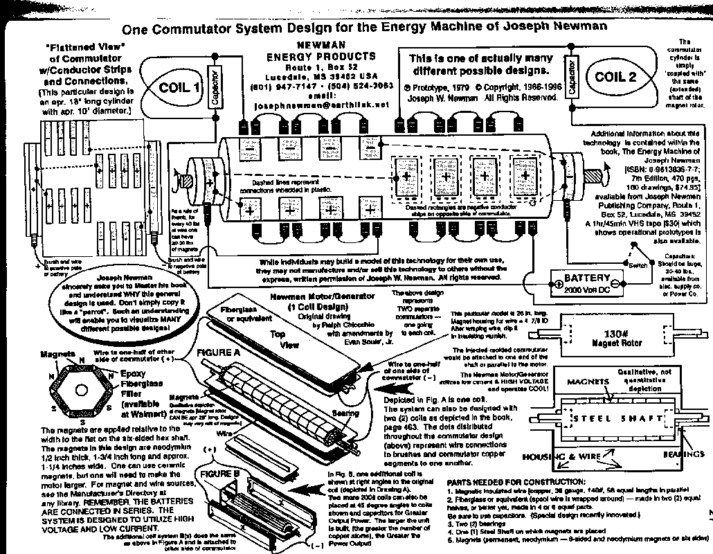
                              I had posted this image before, but website postimg.org made some changes to their domain, so I had to go back and find the missing image and post it here.
                              Attached Files
                              Last edited by vidbid; 05-27-2018, 05:40 AM.
                              Regards,

                              VIDBID

                              Comment


                              • Image

                                Thanks Vidbid,
                                This is best guide to build from. I only built the smaller version so it wasn't much help to me. But I did get some understanding from it. Would been great to see the EV car size J. Newman built. Or how he built it to size.

                                Clarence is building a good looking table top version. Happy building ole friend.

                                Wantomake

                                Comment

                                Working...
                                X