Announcement

Collapse
No announcement yet.

Operating a transformer on DC

Collapse
X
 
  • Filter
  • Time
  • Show
Clear All
new posts

  • Operating a transformer on DC

    If you put AC into the primary of a transformer, you will get AC out of the secondary.

    If you put pulsed DC into the primary of a transformer, you will get AC out of the secondary.

    What I am trying to do is get DC as the output, I know it can be done, I just cant find where I read the solution. Im not talking about putting diodes or rectifiers on the output, Im talking about manipulating the transformer so that the potential does not reverse. Nor am I talking about canceling out the potential by opposing it with another potential.

    I am working from memory here about the solution but this is what I remember.

    1) We can prevent the voltage reversing by pulsing the transformer again as the voltage is dropping to the zero point. In effect our pulse frequency is faster than the resonant frequency of the coil, probably double.
    2) We can prevent the voltage reversing by charging the core of the transformer with a second magnetic field. The same effect as above but without applying a voltage.
    3) Im not sure about this one. By keeping the core strongly polarized magnetically the voltage can be offset. This means that if a 1v pulse is applied to the primary, 2v will be seen in the secondary.
    4) By operating the transformer core close to saturation smaller signals of pulses will result in an offset DC sine wave

    Is anyone familiar with this?

    Can you point me in the right direction to read up on the subject?

    Thanks mike
  • #2
    Hi M,

    See this thread from erfinder

    http://www.energeticforum.com/renewa...tml#post248647

    Garry

    Comment


    • #3
      Originally posted by mbrownn View Post
      If you put AC into the primary of a transformer, you will get AC out of the secondary.

      If you put pulsed DC into the primary of a transformer, you will get AC out of the secondary.

      What I am trying to do is get DC as the output, I know it can be done, I just cant find where I read the solution. Im not talking about putting diodes or rectifiers on the output, Im talking about manipulating the transformer so that the potential does not reverse. Nor am I talking about canceling out the potential by opposing it with another potential.

      I am working from memory here about the solution but this is what I remember.

      1) We can prevent the voltage reversing by pulsing the transformer again as the voltage is dropping to the zero point. In effect our pulse frequency is faster than the resonant frequency of the coil, probably double.
      2) We can prevent the voltage reversing by charging the core of the transformer with a second magnetic field. The same effect as above but without applying a voltage.
      3) Im not sure about this one. By keeping the core strongly polarized magnetically the voltage can be offset. This means that if a 1v pulse is applied to the primary, 2v will be seen in the secondary.
      4) By operating the transformer core close to saturation smaller signals of pulses will result in an offset DC sine wave

      Is anyone familiar with this?

      Can you point me in the right direction to read up on the subject?

      Thanks mike

      Are you saying about pulsed DC as a half-rectified sine wave or as a square wave made from DC ? Are you sure output is AC ? In which case ?

      Comment


      • #4
        Originally posted by boguslaw View Post
        Are you saying about pulsed DC as a half-rectified sine wave or as a square wave made from DC ? Are you sure output is AC ? In which case ?
        Pulsed DC as in square wave around 50% on time.

        During the pulse on time the current ramps up in the primary, during the off time, provided there is a current path, the current ramps down, the coil changes polarity as it is now the source of current.

        The result in the secondary for a 1 v pulse is +1v during the pulse and -1v during the ramp down. Effectively we get an oscillation of 2v peak to peak. Its not really a sine wave but as the voltage and current go first in one direction and then the other I call it AC.

        I experimented with half wave rectified AC but the problem here is I cant get the inductive kickback needed in my circuit so I need the sharp on and off of the pulse.

        Take a look at this graph and imagine the frequency being much higher so there is almost no time when the secondary is at 0v and you will see what i meen. Transformers

        The objective here is to offset the output in the secondary so it is all above or below the line.


        Thanks for the tip Garry

        Comment


        • #5
          so essentially

          it's kick back. have you tried a diode?

          Comment


          • #6
            A diode cannot be used, Ill explain why. This secondary coil also has a DC component, half of the AC created opposes the DC. The effect is that none of the AC can be utilized as an output as the average of the plus and minus is zero.

            I don't want to confuse people with the technicalities of the circuit at this stage but the problem is I cant take advantage of this AC component unless I can make it all go in the same direction of the DC in this coil.

            Comment


            • #7
              This might help

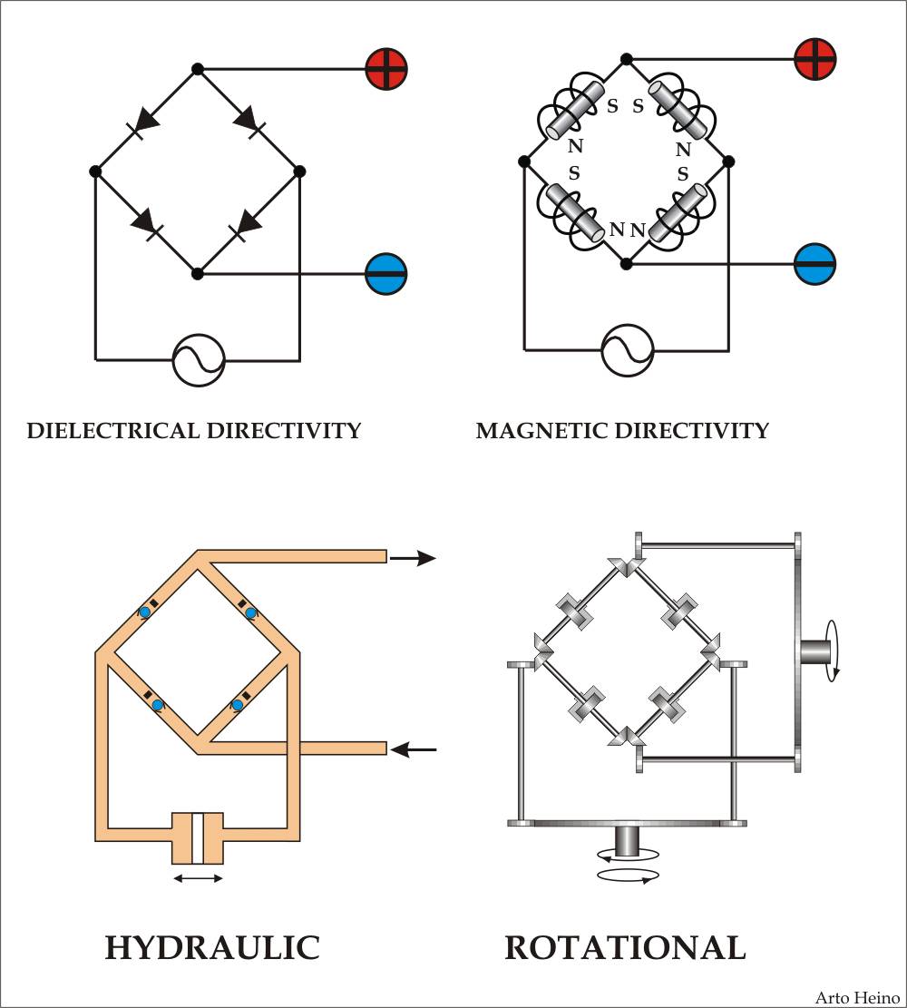
              I have some files that will be put in my next volume, I hope this early sketch of one of my pages will help, Regards Arto

              Talking to the Birds: A Compilation of Essays, Studies and Artwork (Volume 1): Mr Arto Juhani Heino: 9781876406035: Amazon.com: Books

              Comment


              • #8
                Originally posted by mbrownn View Post

                I experimented with half wave rectified AC but the problem here is I cant get the inductive kickback needed in my circuit so I need the sharp on and off of the pulse.


                The objective here is to offset the output in the secondary so it is all above or below the line.
                I think you are talking about the PERIOD = 1/frequency, if you want very sharp on and off then you have to increase the frequency. On the secondary you need only one very fast diode, this will then give you pulsed DC spikes at a period depending on the frequency of input @50% duty.

                eg period = 1/25Mhz= 40nsec (0.00000004seconds)

                Difficult to say without the rest of the circuit, like punching air.

                regards

                Mike

                Comment


                • #9
                  I don't understand ? What is so special about it ? I'm currently working on exactly the same problem and it's called flyback boost converter, well known circuit. A ferrite transformer with a gap store energy during on time and release as inductive spike which generate DC on output. Output is wound in antiphase to input and has a fast recovery diode and a storage capacitor. That way I'm planning to step up from 15V 6A to 345V 0.2A and there are specialized chips available for that.

                  Comment


                  • #10
                    Is this the solution you were looking for ? Flyback converter - Wikipedia, the free encyclopedia

                    Comment


                    • #11
                      Magnetize it

                      Originally posted by mbrownn View Post
                      3) Im not sure about this one. By keeping the core strongly polarized magnetically the voltage can be offset.

                      If the core is kept magnetized in one direction it acts as a back stop. it could be done by having a small magnet acting as a flux diode. It's an alternative to an air gap.

                      Warning tho, if you saturate the core in the wrong spots it may increase power consumption by lowering winding reluctance in your transformer. Look into Mag-amps for answers why.
                      Last edited by Hrothgar; 03-22-2014, 02:26 PM. Reason: warning

                      Comment


                      • #12
                        Originally posted by mbrownn View Post
                        If you put AC into the primary of a transformer, you will get AC out of the secondary.

                        If you put pulsed DC into the primary of a transformer, you will get AC out of the secondary.

                        What I am trying to do is get DC as the output, I know it can be done, I just cant find where I read the solution. Im not talking about putting diodes or rectifiers on the output, Im talking about manipulating the transformer so that the potential does not reverse. Nor am I talking about canceling out the potential by opposing it with another potential.

                        I am working from memory here about the solution but this is what I remember.

                        Thanks mike
                        Check Tesla's solutions.
                        Tesla Patent 413,353 - Method of Obtaining Direct from Alternating Currents

                        Comment


                        • #13
                          Originally posted by Michael John Nunnerley View Post
                          I think you are talking about the PERIOD = 1/frequency, if you want very sharp on and off then you have to increase the frequency. On the secondary you need only one very fast diode, this will then give you pulsed DC spikes at a period depending on the frequency of input @50% duty.

                          eg period = 1/25Mhz= 40nsec (0.00000004seconds)

                          Difficult to say without the rest of the circuit, like punching air.

                          regards

                          Mike
                          Thanks mike but as i say i dont want to block anything with a diode or oppose it either. Frequency may be a solution but I am looking at other possibilities too.

                          I dont have the full circuit, thats what im working out. I have a list of components but not their specifications. I have worked out the geometry of the iron and why it is used this way. This is the last piece of the puzzle, I think

                          (Boguslaw) I don't understand ? What is so special about it ? I'm currently working on exactly the same problem
                          Yes, if we can solve this we are well on our way to solving many of the mystery devices and much more. I dont want to say what it is right now because that will infuence the answers I get here. Possible solutions include inductors, magnetism and frequency, if there is another possibility it may come out here.

                          This interests me
                          a gap store energy during on time
                          What do you mean by that?

                          Imagine if you did not need a diode and consider an inductor instead of a capacitor. I dont know if you could do that in your device but this is how I am thinking. I would try the inductor in series, remember you can manipulate an inductor with magnetism in the core. My transformer and inductors share the same core, this way there is only one set of iron losses. some of the inductors operate 180 degrees out of phase.

                          (Hrothgar) If the core is kept magnetized in one direction it acts as a back stop. it could be done by having a small magnet acting as a flux diode.
                          I suspect this is part of it, but the magnetism is provided by an inductor, not a magnet. My magnetic circuit has 4 air gaps that can be manipulated, I cannot avoid the air gaps as there are moving parts.

                          Erfinder told me to study Mag-amps a year ago, I think its time I did.

                          (Ben 2503) Check Tesla's solutions.
                          Tesla Patent 413,353 - Method of Obtaining Direct from Alternating Currents
                          Thanks Ben, thats one of the patents I was looking for.

                          Comment


                          • #14
                            My device is not a mag-amp, however because of its construction having multiple inductors on the same core, some of the mag-amp interactions will be taking place.

                            A primary inductor is pulsed, the inductive kickback from this inductor is fed into the secondary and both of these conditions have a transformer effect that is passed through to the third output inductor. There will be a lowering of impedance in both the secondary and output coils both in the pulse and in the inductive kickback times.

                            This would be a positive effect as far as I am concerned.

                            The flow of DC current in my output coil would also lower impedance in the primary, this again would be a bonus for me. I have been concerned that all these inductors would prevent an adequate current flow but now I understand why this should not be a problem. The tests I did with only a primary and an output resulted in much higher current flow than I expected and now I know one of the reasons why.

                            A simplified version of what I am doing is a transformer with three windings. The primary is pulsed from an external source, the secondary is pulsed from the inductive kickback from the primary and an output is taken from the third coil. At the same time a magnet is swinging past the output coil causing a DC in this output too

                            I suppose a test rig could be built using a Bedini SSG with a trifilar coil although this device is nothing like a Bedini monopole motor as there are no magnets in the real device. All magnetism is provided by inductors.

                            I hope this simplification helps you understand what is happening and why I have a DC and AC output occurring in the same coil.

                            Comment


                            • #15
                              Originally posted by Hrothgar View Post
                              If the core is kept magnetized in one direction it acts as a back stop. it could be done by having a small magnet acting as a flux diode. It's an alternative to an air gap.

                              Warning tho, if you saturate the core in the wrong spots it may increase power consumption by lowering winding reluctance in your transformer. Look into Mag-amps for answers why.
                              I am interested in this "flux diode" idea as it could offer at least a partial solution. Could you point me in the right direction to read up on this? I have a large inductor which would polarize the device in one direction, this being the primary coil. It is at right angles to the other inductors so Im not sure what effect it will have.

                              As I have four air gaps there may be something that can be done here too, but there isnt much room for adjustment. we are looking at a range of 0.5 to maybe 1.5mm. Currently I was thinking of 0.8mm as an ideal based on the other function of the air gap.

                              Comment

                              Working...
                              X