Announcement

Collapse
No announcement yet.

Electrostatic Induction Generator

Collapse
X
 
  • Filter
  • Time
  • Show
Clear All
new posts

  • #16
    haha, nah no overunity such that there was enough to loop the device and run a small load. I did build many different replicas of various inventors, adams, smith, hectors rotoverters, kunel, etc and have read many more but so far nothing produces OU.

    I went big on the rotoverter stuff... 15hp drive rotoverter belted to a 5kw st style genhead. Hector said he'd work with me to get it setup, and once I acquired the parts he stopped interacting with me. That was the last time I spent big bux trying to trust/replicate.

    I went off into studying periodicity and sequentially sync'ed pulsing. One curiousity that was noted with my 6inch perm mag bedini 6 wire master slave setup was that I could drive one 100watt 120v lamp at full brightness with constant power input from the SG output... or I could add a 50/50 pulser and drive 2 of the lights at half the frequency and still have both lit up fully and not see flicker. That was interesting.

    I also have wandered off into HV HF stuff... with my bellerian apparatus and the ion chair... I'm becoming of the mind that the system will probably need to be comprised of a context circuit, then the circuits within the context to generate the motion... and that the context circuit will likely need to be some sort of hv electrostatic field generation in a local space that is then seeded by some bedini SG's or something to see if that HV spatial charge then combines with the output of the SG perhaps...

    I read the Howard Johnson book, got that from cheniere.org as well. Its interesting... also similar to floyd sweets VTA setup...

    Lots of stuff out there... If you have questions or whatnot maybe I can help or at least offer some ideas... up to you. All I'm about is being helpful and reducing suffering...

    Take care,
    Gene

    Originally posted by BroMikey View Post
    Awe come on gene. Did you ever get OU on one of your projects? You sound very well schooled. Did you go big on one of these generators? Did you build one?

    Mikey

    Comment


    • #17
      [VIDEO]https://www.youtube.com/watch?v=pJ36EtABLAk[/VIDEO]

      Charge and discharge.
      Regards,

      VIDBID

      Comment


      • #18
        Still needs the Source to charge from huh. (so one can stand there and rub fur on teflon to generate the electric dipole... or whatever, but it takes input. The smarter alternative would be to make use of the point-sphere model and embed in the concentric shells which already intrinsically show the volt potential) The clouds move past the Ground, relative motion, inducing charge. Two people dancing, relative motion of different fabrics generating friction and thus thermal and or electrostatic potentials.

        Find the best relatively localized potential and tap it. (or a source of motion that can be adapted to do work inducing electrical charge separation.)

        Gene

        Originally posted by vidbid View Post
        [VIDEO]https://www.youtube.com/watch?v=pJ36EtABLAk[/VIDEO]

        Charge and discharge.

        Comment


        • #19
          Free Ride Replica's

          Originally posted by genessc View Post
          haha, nah no overunity such that there was enough to loop the device and run a small load.
          Ah-Hah!! so you did get the extra, I knew it. Looping comes later.


          Originally posted by genessc View Post
          I did build many different replicas of various inventors, adams, smith, hectors rotoverters, kunel, etc and have read many more but so far nothing produces OU.
          You gotta admire a man for riding these donkey's in search of OU, then "I've been through the desert on a horse with no name" Also. It's lonely out here.


          Originally posted by genessc View Post
          I went big on the rotoverter stuff... 15hp drive rotoverter belted to a 5kw st style genhead. Hector said he'd work with me to get it setup, and once I acquired the parts he stopped interacting with me. That was the last time I spent big bux trying to trust/replicate.
          They tell me for the last 30 years that what I have been doing to start and run 3 phase motors on 2 phase power is a "ROTO-VERTER"? Okay well, if you say so I replied. Then some say you can power your house on it. Well one circuit off the box

          Thats when I say, I have two 100hp electric motors and two 20hp ones.But I don't see anyone doing this after 40 years


          Originally posted by genessc View Post
          I went off into studying periodicity and sequentially sync'ed pulsing.
          Now that sounds like Beardon stuff, sneak in there in between pulses or standing wave harmonics? You got me on that one, I need more info.


          Originally posted by genessc View Post
          One curiousity that was noted with my 6inch perm mag bedini 6 wire master slave setup was that I could drive one 100watt 120v lamp at full brightness with constant power input from the SG output... or I could add a 50/50 pulser and drive 2 of the lights at half the frequency and still have both lit up fully and not see flicker. That was interesting.
          Yes even a tiny circuit found in the bottom of an inverter CFL bulb is capable of 120 volts just foolin, I know what you mean. You meant that for the amount of power going into the wheel you were surprised that you were getting a 100watt bulb lit?


          Originally posted by genessc View Post
          I also have wandered off into HV HF stuff... with my bellerian apparatus and the ion chair... I'm becoming of the mind that the system will probably need to be comprised of a context circuit, then the circuits within the context to generate the motion... and that the context circuit will likely need to be some sort of hv electrostatic field generation in a local space that is then seeded by some bedini SG's or something to see if that HV spatial charge then combines with the output of the SG perhaps...
          That sorta sounds like the EV Gray stuff where high frequency/high voltage charges are made in interact with low voltage side to create torsion and thus aether correction.


          Originally posted by genessc View Post
          I read the Howard Johnson book, got that from cheniere.org as well. Its interesting... also similar to floyd sweets VTA setup...

          Lots of stuff out there... If you have questions or whatnot maybe I can help or at least offer some ideas... up to you. All I'm about is being helpful and reducing suffering...


          yeah they all got more out, didn't they?
          Last edited by BroMikey; 02-27-2015, 09:42 PM.

          Comment


          • #20
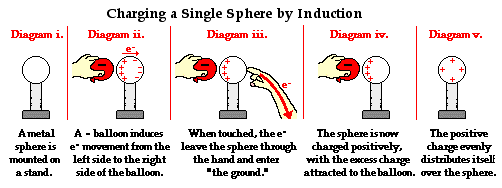
            Charging Rod and Electroscope

            Originally posted by genessc View Post
            Still needs the Source to charge from
            The positive charge is never depleted in the charging by induction example.

            Step 1. zero charged electroscope.


            ______________________________

            Step 2. Introduce positive charged rod near but not touching the electroscope. This causes charge separation in the electroscope.


            ______________________________

            Step 3. Connect the ground.


            ______________________________

            Step 4. Disconnect the ground.


            ______________________________

            Step 5. Remove the charging rod away from near the top of the electroscope.


            ______________________________

            Step 6. Now the electroscope is now negatively charged.


            ______________________________

            At the point, you could add a Step 7 to send the negative charge from the electroscope through a load to ground.

            The load could be an electrolysis cell.

            You get the idea.
            Regards,

            VIDBID

            Comment


            • #21


              Here's another example of it, however, with a negative charging structure.
              Regards,

              VIDBID

              Comment


              • #22
                I don't know that the fast charging of the capacitors on the bedini setups constitutes overunity. You end up having to account for the input draw in pulsed quanta against the output charged capacities pulsed frequency and see whats there. Really its sorta like those guys who made the battery that always recovers just enough charge to fire and ring the bell once more, but that battery is being "used" in pulses, and is allowed a recharge time that takes however long in relation to the actual discharge length of time.

                That 3phase motor on single phase AC, yeah they call that the rotoverter. Then theres the RV Alternator which is the other 3phase AC motor nose coupled to the drive motor that uses an exciting capacity between two legs of its 3 phases to "reverse induce" VARS into the RV Alternator... I have a pair of 7.5hp 3phase motors on a bench from that work. Extracting energy from that setup Always reflected to the input of the RV prime mover such that it nulled out any gain that might have been noted. I set that aside, tho I know Doug Konzen on EVGRAY yahoogroups is still working at that along with Ashtweth over at panacea-bocaf.

                Periodicity is my own term, that I came up with to note the arbitrary definition of pulse trains or pulse sequences that have some number of pulses and then repeat from the beginning.

                The reference to the 100w lamp being lit, and then with the same input power the 2 x 100w lamps being lit, was due the frequencies achieved. Our eyes generally catch images at 24frames per second. So long as the pulses into the lamps are about double that, you don't detect the flickering of the lamps, even if they are flickering because we can't see any "faster"... theres just some period of time that our vision requires before the next frame is sorted and then we blur it together to see the world as full of change. So technically it was still the same 100watts of power, but because the sg runs at about 300hz I could output at 120hz alternating with the 50/50 opposing on times and to my eyes, the lamps were both just lit. This would be different on the 60hz mains, even rectified to 120hz because you need multiple pulses on the front end to have enough collected on the back end during discharge to do work. Its sort of a pulse down conversion, much like the bedini 6,545,444 original patent used the SG's multiple pulses to charge up the capacitor that was then discharged at a 5-15hz rate 50% duty into the batteries, this being an accumulation from the higher frequency SG's output.

                The CFL circuit board outputs 300-500volts to be able to breakover the mercury vapor in the phosphor tube, so you need at least 120vdc input to let it spool up and fire properly. Theres also some frequency upconversion done by that little circuit.

                And nope, they All didn't get more out. Some got an additional 10% and maybe up to 30% but nobodies looped.

                The one thing I would like to maybe get tho is one of bedinis solar chargers, those are supposedly able to deliver big amp impulses due how he matched transistors in them using solar as input. I got all those 35,000uF 35vdc lytic caps cuz I was gonna try and reproduce but I could never get the big amp discharges like he showed on his video of those solar chargers.

                On that 20hp motor, my 15hp motor needed about 600uF ac run caps switched in to "Start" the motor up, and then that would all get switched out and it ran on like 120-145uF capacity. What do you end up using to connect the second to 3rd phase on your 20hp 3phase motor, in terms of capacity, to let it run after that starting current subsides at rpm?

                Cheers.
                Gene


                Originally posted by BroMikey View Post
                Ah-Hah!! so you did get the extra, I knew it. Looping comes later.

                You gotta admire a man for riding these donkey's in search of OU, then "I've been through the desert on a horse with no name" Also. It's lonely out here.

                They tell me for the last 30 years that what I have been doing to start and run 3 phase motors on 2 phase power is a "ROTO-VERTER"? Okay well, if you say so I replied. Then some say you can power your house on it. Well one circuit off the box

                Thats when I say, I have two 100hp electric motors and two 20hp ones.But I don't see anyone doing this after 40 years


                Now that sounds like Beardon stuff, sneak in there in between pulses or standing wave harmonics? You got me on that one, I need more info.


                Yes even a tiny circuit found in the bottom of an inverter CFL bulb is capable of 120 volts just foolin, I know what you mean. You meant that for the amount of power going into the wheel you were surprised that you were getting a 100watt bulb lit?


                That sorta sounds like the EV Gray stuff where high frequency/high voltage charges are made in interact with low voltage side to create torsion and thus aether correction.


                yeah they all got more out, didn't they?[/FONT][/SIZE]

                Comment


                • #23
                  If that was true, it would just keep on spinning wouldn't it. I think my eyes are more trustworthy than some physicists claim. No worries tho if thats the tact you want to take.

                  Gene

                  Originally posted by vidbid View Post
                  The positive charge is never depleted in the charging by induction example.

                  Comment


                  • #24
                    Let me insert my thoughts next to >>> in the quote of your details below.

                    Originally posted by vidbid View Post
                    The positive charge is never depleted in the charging by induction example.

                    Step 1. zero charged electroscope.


                    ______________________________

                    Step 2. Introduce positive charged rod near but not touching the electroscope. This causes charge separation in the electroscope.


                    >>> this "requirement to bring near but not touch" is what brings the charge which branches out from the charged rod in leaders is brought close enough for the positive offset charge to affect a charging of the electroscope. The charge separation is because the whole of the conductive part of the electroscope is charged with a balanced LIKE potential, and its that same potential that causes the leaves to separate.
                    ______________________________

                    Step 3. Connect the ground.


                    >>> This causes the electroscopes charged state to become balanced with the EARTH which it is then put into direct Conductive relation with. Because it is now charged to the same potential as the earth the charged potential has exchanged both positive and negative charge to neutralize the electroscope and let the leaves come back together. However note the charged rod is still above the electroscopes knob so now the electroscope has an excess of negative charge from the earths ground on it because of that charged rods local presence at the top of the electroscope.
                    ______________________________

                    Step 4. Disconnect the ground.


                    >>> This just re-isolates the electroscope from the earth.
                    ______________________________

                    Step 5. Remove the charging rod away from near the top of the electroscope.


                    >>>Now that the electroscope had to accumulate an increase in negative charges while the charged rod was held local to the conductive top of the electroscope and the earth ground was connected conductively to the electroscope, when the positive charged rod is removed, the now seeming "excess" of negative charges no longer held in balance by its relation to the charged rod end that was just prior local to it, now allows the negative to own its own imbalanced state as being dominant in the electroscope, which again is what causes the leaves to separate.
                    ______________________________

                    Step 6. Now the electroscope is now negatively charged.


                    >>> yup, but not because it Gained more charge magically, but because the local positive charge end which held the charge potential of the electroscope in balance just prior, had been removed. Presumably moving the charged rod back would bring the leaves back together as the charges move back into a balanced state with that thing external to itself.
                    ______________________________

                    At the point, you could add a Step 7 to send the negative charge from the electroscope through a load to ground.

                    The load could be an electrolysis cell.

                    You get the idea.

                    Anyways hope that helps you understand the Why of it. Some small quanta of the charging thing is Always transferred to the thing being charged, even if theres some small gap, as at that point the volt potential of the charged rod is in the thousands of volts but at microcurrents of actual current potential..... and it transfers to induce charge. Just need better means of measuring to show this to be the case. (given the air ion transfer which is happening the best way would probably be to measure the ion count locally and see how that changes as this test is repeated with different variances applied.)

                    Cheers.
                    Gene

                    Comment


                    • #25
                      What?

                      Originally posted by genessc View Post
                      If that was true, it would just keep on spinning wouldn't it.
                      There is nothing spinning in the induction example that I was referring to.

                      The device pictured in the first post of this thread is a motor, not a generator.

                      In the video, the positively charged rod holds a positive charge and is not depleted of its positive charge.

                      Take a look at the video at 3 minutes and 45 seconds.

                      [VIDEO]https://www.youtube.com/watch?v=pJ36EtABLAk&t=3m45s[/VIDEO]

                      IMHO, the device pictured in the video is a generator because it produces charge through induction.
                      Last edited by vidbid; 02-28-2015, 03:58 AM.
                      Regards,

                      VIDBID

                      Comment


                      • #26
                        Originally posted by genessc View Post
                        I don't know that the fast charging of the capacitors on the bedini setups constitutes overunity. .................................................. .....................

                        Yeah that is a great starting point.


                        Originally posted by genessc View Post
                        The one thing I would like to maybe get tho is one of bedinis solar chargers, those are supposedly able to deliver big amp impulses due how he matched transistors in them using solar as input. I got all those 35,000uF 35vdc lytic caps cuz I was gonna try and reproduce but I could never get the big amp discharges like he showed on his video of those solar chargers.

                        John is amplifying energy into batteries. I talked to him one time only and he said that I could order one WITH other designs all in one package. John uses 24 PNP transistor devices with each in and out trace on the transistor being around a 14awg wire. Take 24 wires and add them together on the drains and how big is the cable? Take 24 wires/traces off the source and add them all together to get a giant cable able to handle hundreds of amps.

                        Of course cap play a part but not much as John is sending energy splatter/noise right off the amplifier transistors to do the job. It is a glorified regulator.


                        https://www.youtube.com/watch?v=y93IwhOGWB4


                        Last edited by BroMikey; 02-28-2015, 03:37 AM.

                        Comment


                        • #27
                          In an open system electrostatic handling is important and unlike
                          a closed system where losses are measured in magnetic.
                          Dielectric in a magnetic world can take on illusive forms.

                          In Van de graaf experiments leak is an important factor.
                          The example of standing on an 8 inch stool makes large difference.

                          Reducing the leak back to the ground can allow a dipole to build up.
                          The ability to reduce leaks in order to isolate charge is often overlooked
                          in many experiments the technician had a large quantity of dielectric component but scratched his head wondering where it went.
                          When the electrostatic field does leak it does it in a big way
                          usually without our notice.

                          An electrostatic induction generator is a great tool for finding leaks.
                          Sometimes finding optimum distance between components using strong induced electrostatic field allows a weak field condition to be optimized.
                          In harvesting energy in nature or designing instrumentation to measure disturbances same principal may be helpful.

                          Comment


                          • #28
                            Here is a link to the Steele Braden thread I started a while back.

                            http://www.energeticforum.com/renewa...=Steele+Braden

                            As I said before, Steele IS an electrical engineer, and researched this for may years. It DOES work. The only limitations are in how well you are able to construct it and the SIZE determines the output.

                            I am STILL going to replicate this and have all the parts. Hopefully in the next few weeks as I get my shop organized I will have the time to work on it.

                            Dave
                            “Advances are made by answering questions. Discoveries are made by questioning answers.”
                            —Bernhard Haisch, Astrophysicist

                            Comment


                            • #29
                              Reminder Links

                              Thank Dave, For reminding me. I don't know what it does yet.


                              Originally posted by Turion View Post
                              Here is a link to the Steele Braden thread I started a while back.

                              http://www.energeticforum.com/renewa...=Steele+Braden

                              As I said before, Steele IS an electrical engineer, and researched this for may years. It DOES work. The only limitations are in how well you are able to construct it and the SIZE determines the output.

                              I am STILL going to replicate this and have all the parts. Hopefully in the next few weeks as I get my shop organized I will have the time to work on it.

                              Dave

                              Comment


                              • #30
                                Repost

                                This is an alternator (generator) that CANCELS out ALL BACK-TORQUE. 
The only work that the small drive motor has to do is overcome very small air and bearing friction.
As you know, all “standard” alternators, produce back-torque when an electrical load is connected to their output.
The lower the resistance of the load, the more mechanical energy that has to be put into rotating the alternators shaft. 
My machine on the other hand, has no connection between the rotational energy requirements of the small drive motor and the output energy.
Basically, two rotary capacitors that are 180 degrees out of step with each other, RECYCLE a charge back and forth between them indefinitely.
When one rotary capacitor is fully “meshed” (maximum capacitance,) the other cap. is unmeshed (minimum capacitance.)
To placate the “conservation of energy” guys, this machine certainly conserves power, in that it RECYCLES power, so does not deplete the initially placed charge.
The machine would normally lose about 9 microamps through imperfect insulation etc, but the machine also keeps the HT charge topped up.
 My machine is only small, so not very practical, but a larger machine would produce some useful output. 
For every 440 picofarads swing, 20 watts flows.
This is at high voltage and low current AC and has to be stepped down (e.g. 12 volts) where the current rises to something useful.

                                Thus the small drive motor “feels” no work other than very small bearing and air friction. The output of the machine has no relationship to the rotational energy requirements of the drive motor, so the word “efficiency” has no meaning. Efficiency, normally applies to the ratio between input power and output power.

                                My machine consists of two rotary capacitors, but a practical output machine would have many sets of rotary caps. My present prototype has two rotors of Perspex (acrylic) 300mm in diameter sandwitched between two square “plates” as the stators on the left, and the same on the right. These two rotor discs are connected via a shaft with insulated coupling in the centre. The rotors have 6 “petals” of aluminium foil on them (both sides) as do the inner sides of the stator plates. The acrylic is all 4mm thick. The stators have a covering on their surfaces of 2mm thick acrylic to prevent arc-over, as a high voltage exists here. When one rotors petals are exactly in line with its stator petals, (fully meshed) position, this rotary capacitor is at its maximum capacitance. At the same time, the other rotary cap. is fully unmeshed and at its lowest capacitance. In other words, both rotary capacitors are always at 180 degrees out of synch. with each other. An initial HT charge is placed on the machine from a momentary external supply, then removed. The load, is connected in series with both the rotors. As the rotors are rotated, the fully meshed capacitor is unmeshed while the other rotor is now going into mesh. This causes the unmeshing rotor to transfer its charge over to the meshing capacitor. This results in an AC current going back and forth between the two rotary capacitors indefinitely. The power is high voltage at low current, so to be a practical output, it needs to be stepped down via a transformer to something useful e.g. 12 volts, whilst at the same time, the current rises to again something useful. I, without using a step-down transformer, used two 8 watt fluo. tubes in series as a load. These stayed illuminated for 4 hours without diminishing in brightness, till I stopped the test. Because my machine is only small, there is not enough output to “close the loop” i.e. take the output and feed it to the drive motor to make the system self-sustaining. A larger machine would have enough output to be self sustaining.

                                If this was yet just another alternator, there would be no point to it. THE point of this machine, is that it has no back-torque – in other words, the drive motor has no work to do as in conventional alternators where you have to fight the drag of the back-emf. The following, is the secret of cancellation of all back torque: The unmeshing rotor, DOES experience electrostatic back drag, BUT at this same instant, the rotor going INTO mesh, experiences attraction assistance electrostatic pull in closing. These two forces are identical and so CANCEL EACH OTHER OUT !!! At 300 rpm, the machine outputs 50 hz. For a greater output machine, there are several options. Increase the rpm. Increase the number of pairs of rotary capacitors. Increase the diameter of the rotors. Reduce the air gap between the rotors and the stators.

                                I believe Doubling the diameter of the rotors provides FOUR TIMES the output. Halving the air gap provides FOUR TIMES the output. Doubling the rpm, doubles the output. Because of imperfect insulation etc. the machine would loose 9 microamps, however, the machine also acts as a DC generator and keeps the HT charge topped up. There is no heat in this machine and it is very quiet to run. I have experimented with many variables in the number of aluminium foil petals, but it appears that 6 is the optimum. If you are interested in building this machine, I can also supply photographs and the associated circuit diagrams.

                                As you know, capacitors are open-circuit devices, so cannot loose their charge. My circuit never has a capacitor connected via its terminals directly to the load. Instead, the capacitors are connected in series and in series with the load. The load only gets power when the rotary capacitors are actually rotating and sending the current back and forth between them There ARE losses, but the machine also works as a HT DC generator which tops up the otherwise wasted HT losses.

                                Turion

                                Comment

                                Working...
                                X