Announcement

Collapse
No announcement yet.

COP 20.0 (2000%) Demonstration

Collapse
X
 
  • Filter
  • Time
  • Show
Clear All
new posts

  • #16
    Thnx for the info/help Farmhand! I appreciate it

    I will study this more.

    Greets JB


    Originally posted by Farmhand View Post
    Here Johnny, Here is a reference paper and other links to help you understand.

    Reactive power paper
    http://www.uksldc.org/Download/reactive_power.pdf

    True, Reactive, and Apparent power : Power Factor


    Basically when we have different loads on an AC supply the phase angle
    between voltage and current changes, when the phase angle is 0 degrees the power
    Factor is 1.0 and all energy transferred to the load is consumed by the load none
    is returned to the supply, all power transferred is "real" power or "true" power,
    it got used.


    However if the load is other than purely resistive like a motor the phase angle between
    voltage and current will change and some of the energy transferred to the
    motor will be released and return to the supply, that is reactive power it is
    energy not dissipated by the load and is transferred back to the supply, simply
    put. And at a Phase difference of 90 degrees between voltage and current
    the power factor is 0.0 and no energy can be transferred.

    If the phase difference of V and Current is eg. 60 degrees then 60 x cosine = 0.5 power factor,
    so 50 % of the applied or apparent power is not dissipated in the load and
    transferred back to the supply.

    Now we can easily make provision to convert that reactive power back into real power and dissipate it in a load already.

    I could probably find Tesla's own words from a book where he states that the
    closer the real power value (consumed power) is to the apparent power
    (power initially applied) then the better the system is working, meaning he
    tried to minimize reactive power to improve efficiency.

    By definition reactive power becomes real power the instant it is consumed or used.

    I thought Eric Dollard said there was no free energy fuse box.

    Cheers
    http://youtube.com/johnnblade

    Comment


    • #17
      Hi Aaron,

      Thnx for your explanation to, good to visualize it

      My experiment is the Tesla Patent 381.970 aka System of Electrical distribution or the Alternating Current Magneto Machine.

      If my phases are not tuned properly then it starts to add more amps on input, but when properly tuned, the amps on input does not get affected by the load.

      Has this something to do with when Tesla used 2 or 4 phases, but he saw he could use 1 phase by just only adding a resistor to make it 2 phases, thus making the device a bit more efficient ( or am i totally wrong here? )

      I will study all this more, cause i really want to understand this in depth.


      Greets JB


      Originally posted by Aaron View Post
      @Mike - thank you!

      @JB, hard for me to see really what your experiment is, but I'll explain power factor in terms that made sense to me. Farmhand is right on the definition, but I'll add something to it.

      @Farmhand, I understand your explanation about power factor but I'll throw in the horse/rail analogy. I believe Eric saying there is no free energy fusebox was a matter of semantics because he doesn't believe in "free energy". He does however talk about energy synthesis and de-synthesis. Occasionally, he will casually mention the "free energy fusebox" but that is not in any technical discussion, just a reference to what it is referenced as. Yes, it exists, and is self-runs and keeps the batteries charged up by whatever name you want to call it - completely real "free energy" "overunity" self running device.

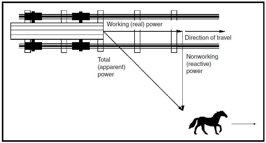
      For power factor - there is a common analogy.... if there is a traincar on some tracks and the horse pulling it is not on the tracks but off at a 45 degree angle for example, and the horse moves forward, the traincar will still move down the tracks, but there is still this incongruity between the horse and its angle in relation to the traincar. The move forward, work is being done, but not very efficiently. The power factor would be like 0.5 or so.

      However, if the horse moves over and onto the tracks so that it is in perfect alignment with the train and both are moving forward, the train can move with less energy being wasted and if they're perfectly aligned, that is like a power factor of 1.0.

      It isn't a perfect analogy because I would argue that the reactive power in the horse/traincar example is bogus because work IS being done. The horse has to work harder to pull the car the same. But the point is that it isn't being consumed by the train, which is the intended load. So I guess this extra work is "returned to the source" which is the horse so it is still a pretty good analogy.

      If you have bad power factor loads, it does strain the power company more. One of my friends here was a linesman and he used to put "snoops" on the line when the power company thought some company had too bad of a power factor. They will penalize the company for that bad power factor causing problems at the generator end and if it isn't corrected, they will even shut off the power completely.

      Again, this is my total layman explanation but you have experienced these discrepencies between the voltage and current yourself but probably didn't know that is what it was.

      When an old refrigerator (compressor motor is inductive load) kicks on, the lights might dim for a moment then it goes normal. That surge is a discrepancy between the voltage and current running the inductive load then it normalizes to a point. If there is a capacitor that is tuned for the load on the line between that compressor motor and the wall, that capacitor will be like a buffer that normalizes that power factor so there isn't a surge on the line and the power factor is corrected.

      Many inductive loads are already power factor corrected like the CFL bulbs from Europe (probably not in the states), newer refrigerators I believe, etc... so bad power factor isn't as bad as it used to be.

      Another friend worked at an electrical billing center in my town that does billing for major department stores all over the country, etc... and it lists their average power factor. Some are as low as .6, .7 (some worse) - that means they are paying for electricity that are not even using and by simply power factor correcting their loads, they will save a fortune. I'm talking about companies spending 5-6 figures a month on electricity.

      @All, if this explanation is incorrect, please jump in.

      http://youtube.com/johnnblade

      Comment


      • #18
        Originally posted by Aaron View Post
        @Mike - thank you!

        @JB, hard for me to see really what your experiment is, but I'll explain power factor in terms that made sense to me. Farmhand is right on the definition, but I'll add something to it.

        @Farmhand, I understand your explanation about power factor but I'll throw in the horse/rail analogy. I believe Eric saying there is no free energy fusebox was a matter of semantics because he doesn't believe in "free energy". He does however talk about energy synthesis and de-synthesis. Occasionally, he will casually mention the "free energy fusebox" but that is not in any technical discussion, just a reference to what it is referenced as. Yes, it exists, and is self-runs and keeps the batteries charged up by whatever name you want to call it - completely real "free energy" "overunity" self running device.

        For power factor - there is a common analogy.... if there is a traincar on some tracks and the horse pulling it is not on the tracks but off at a 45 degree angle for example, and the horse moves forward, the traincar will still move down the tracks, but there is still this incongruity between the horse and its angle in relation to the traincar. The move forward, work is being done, but not very efficiently. The power factor would be like 0.5 or so.

        However, if the horse moves over and onto the tracks so that it is in perfect alignment with the train and both are moving forward, the train can move with less energy being wasted and if they're perfectly aligned, that is like a power factor of 1.0.

        It isn't a perfect analogy because I would argue that the reactive power in the horse/traincar example is bogus because work IS being done. The horse has to work harder to pull the car the same. But the point is that it isn't being consumed by the train, which is the intended load. So I guess this extra work is "returned to the source" which is the horse so it is still a pretty good analogy.

        If you have bad power factor loads, it does strain the power company more. One of my friends here was a linesman and he used to put "snoops" on the line when the power company thought some company had too bad of a power factor. They will penalize the company for that bad power factor causing problems at the generator end and if it isn't corrected, they will even shut off the power completely.

        Again, this is my total layman explanation but you have experienced these discrepencies between the voltage and current yourself but probably didn't know that is what it was.

        When an old refrigerator (compressor motor is inductive load) kicks on, the lights might dim for a moment then it goes normal. That surge is a discrepancy between the voltage and current running the inductive load then it normalizes to a point. If there is a capacitor that is tuned for the load on the line between that compressor motor and the wall, that capacitor will be like a buffer that normalizes that power factor so there isn't a surge on the line and the power factor is corrected.

        Many inductive loads are already power factor corrected like the CFL bulbs from Europe (probably not in the states), newer refrigerators I believe, etc... so bad power factor isn't as bad as it used to be.

        Another friend worked at an electrical billing center in my town that does billing for major department stores all over the country, etc... and it lists their average power factor. Some are as low as .6, .7 (some worse) - that means they are paying for electricity that are not even using and by simply power factor correcting their loads, they will save a fortune. I'm talking about companies spending 5-6 figures a month on electricity.

        @All, if this explanation is incorrect, please jump in.

        .
        .

        This is very elegant, but something worries me: Is "work done" a scalar quantity or a vector quantity? (It is a dot product of two vectors - or have I got this wrong?).
        .
        .
        Last edited by wrtner; 05-07-2014, 04:06 PM.

        Comment


        • #19
          The devise consists of a controller module, a switching module and a capacitor bank. Jim Murray states:

          "Maxwell thought that all the electrical energy was carried in the magnetic and electrical fields. 30 years later Einstein and De Haas found that there was addition energy that was carried by the current itself and not by the fields. (They decided not to correct this.)

          In a normal situation the reactive power is defined as a form of restorative power in which the average value is zero. The problem with that is the current and voltages are usually out of phase by 90 degrees so that you cannot use it. What this devise allows you to do is create watts that go back and forth doing the same thing and the watts become reactive."

          What I think is that they are capturing the extra energy that is carried by the current by controlling when to switch, storing this in the capacitors. They developed a phase and wattage algorithm that returns a value that allows the switching to mimic an ideal transformer reactance, also more than power factor correction because the extra energy is made available and the wave form on the oscilloscope shows the product. The other channel uses a current probe shows the current lag or lead for the inductive resistive load.

          Understanding why the extra energy breaks away from the E and M fields and takes another pathway would be helpful information to design transformers and use
          materials in such a way that the majority of machines would never go out of phase. This really means replacing the old technology. I see a few that use Tesla
          and new methods and have made progress.
          Last edited by mikrovolt; 05-07-2014, 06:52 PM.

          Comment


          • #20
            The 22 inch coax from the signal generator connected capacitor made from a thin sheet metal 3” x 3” another sheet metal has an air space ¼ to 3/4 “ the second sheet metal connects to a 245 uH aircore inductor 100 Turns #30 on 1.25” dia. Uses 33’ wire. This is a series tank for 3.2 Mhz HF VTTC and does not need pi filter. Optimize only!. For 1.85Mhz use a 690uH inductor. Later the Impedance match is between the amplifier and the primary. Please understand that you design with specific values and declaring values going into the project sets a goal but the result may be off which is ok. If you don’t have a network analyzer it does not prevent you from success just time consuming. As said before you work back and forth.

            Comment


            • #21
              Thanks for expressing this

              Originally posted by mikrovolt View Post
              The devise consists of a controller module, a switching module and a capacitor bank. Jim Murray states:

              "Maxwell thought that all the electrical energy was carried in the magnetic and electrical fields. 30 years later Einstein and De Haas found that there was addition energy that was carried by the current itself and not by the fields. (They decided not to correct this.)

              In a normal situation the reactive power is defined as a form of restorative power in which the average value is zero. The problem with that is the current and voltages are usually out of phase by 90 degrees so that you cannot use it. What this devise allows you to do is create watts that go back and forth doing the same thing and the watts become reactive."

              What I think is that they are capturing the extra energy that is carried by the current by controlling when to switch, storing this in the capacitors. They developed a phase and wattage algorithm that returns a value that allows the switching to mimic an ideal transformer reactance, also more than power factor correction because the extra energy is made available and the wave form on the oscilloscope shows the product. The other channel uses a current probe shows the current lag or lead for the inductive resistive load.

              Understanding why the extra energy breaks away from the E and M fields and takes another pathway would be helpful information to design transformers and use
              materials in such a way that the majority of machines would never go out of phase. This really means replacing the old technology. I see a few that use Tesla
              and new methods and have made progress.
              Hi Mikrovolt
              Good explanation, simple which is always best. This also brings me to why cap dumping at varying rates applies to your subject matter. I think sometimes as I adjust my pulse timing to set up a standing wave that the reflected power meets up with the next pulse and somehow does strange things.

              We all know how capacitors effect phasing and that many inventors have pointed out the need to switch at the right time. Of course the cap dump is a basic tool with promise and is not as advanced as what the discussion is about concerning this invention.

              And like you said we don't always know why but rather through experimental trials a given phenomena is stumbled upon. At first only a small change is detected and then it is developed over the years of application.

              Mike

              Comment


              • #22
                Hi all,
                I am not sure if i have understood this device but does the phasedifference not only mean that the counter for the electricity doesn`t "see" the real power that is used?I mean when you close the loop with a batterydriven device the battery simply runs down?
                Thanks for clarification.

                Comment


                • #23
                  Originally posted by mikrovolt View Post
                  The 22 inch coax from the signal generator connected capacitor made from a thin sheet metal 3” x 3” another sheet metal has an air space ¼ to 3/4 “ the second sheet metal connects to a 245 uH aircore inductor 100 Turns #30 on 1.25” dia. Uses 33’ wire. This is a series tank for 3.2 Mhz HF VTTC and does not need pi filter. Optimize only!. For 1.85Mhz use a 690uH inductor. Later the Impedance match is between the amplifier and the primary. Please understand that you design with specific values and declaring values going into the project sets a goal but the result may be off which is ok. If you don’t have a network analyzer it does not prevent you from success just time consuming. As said before you work back and forth.
                  I posted this in the wrong thread. Also in the video the person speaking is probably not Jim Murray(inventor of the dynaflux alternator), I apologize.

                  The current probe for an oscilloscope displayed on channel A while channel B is voltage can be made easily show lead or lag. see figure 4 or 5.
                  The HF Current Probe: Theory and Application
                  Last edited by mikrovolt; 05-21-2014, 07:41 AM.

                  Comment


                  • #24
                    Jim Murray Dynaflux Alternator

                    That is Jim Murray who invented the Dynaflux Alternator and we're going to make the whole demo available, etc... probably next weekend.
                    Sincerely,
                    Aaron Murakami

                    Books & Videos https://emediapress.com
                    Conference http://energyscienceconference.com
                    RPX & MWO http://vril.io

                    Comment


                    • #25
                      successful replication

                      Yesterday, I saw the first successful replication of this device. It wasn't as high as COP 20.0 but is very important because it proves it is not some fluke - it is completely engineerable.
                      Sincerely,
                      Aaron Murakami

                      Books & Videos https://emediapress.com
                      Conference http://energyscienceconference.com
                      RPX & MWO http://vril.io

                      Comment


                      • #26
                        Any more details Aaron? Was this someone independent of Jim and Paul? I want to engineer this thing also.

                        I understand basic reactive power from college.... but even after watching all of Jim's videos I could find, not quite getting how this "reactive watts" works? Power is in the current and not the fields? Luc Choquette on YouTube seemed to be going in the right direction but later claimed it was a measurement error.

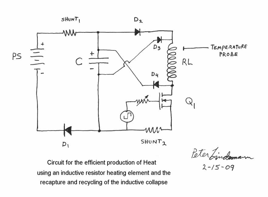
                        The 20 COP video that Jim made kind of reminds me of Lindemann's high COP circuit... minus the coil transformers.


                        Can't wait to see what these guys unveil!

                        Originally posted by Aaron View Post
                        Yesterday, I saw the first successful replication of this device. It wasn't as high as COP 20.0 but is very important because it proves it is not some fluke - it is completely engineerable.
                        Last edited by SilverToGold; 05-26-2014, 01:05 AM.

                        Comment


                        • #27
                          reactive power

                          Originally posted by SilverToGold View Post
                          Any more details Aaron? Was this someone independent of Jim and Paul? I want to engineer this thing also.

                          I understand basic reactive power from college.... but even after watching all of Jim's videos I could find, not quite getting how this "reactive watts" works? Power is in the current and not the fields? Luc Choquette on YouTube seemed to be going in the right direction but later claimed it was a measurement error.

                          The 20 COP video that Jim made kind of reminds me of Lindemann's high COP circuit... minus the coil transformers.

                          Can't wait to see what these guys unveil!
                          Jim's methods are unrelated to the Ainslie type circuits, which use the inductive spike from an inductive resistor to send back to input source. The resistors on Jim's is there to show real work - the resistors were burning hot and I even took a picture with my thermal imaging camera - no mistake about it... real work is being done that is undeniably more than what is drawn from the wall.

                          I did actually bring up the Ainslie type circuit with Peter yesterday because something about Jim's SERP technology inspired me but I'd have to do some experiments to see if even one of the concepts can be applied to it (Ainslie) to improve the desired gain. I'll do this in all my spare time lol.

                          One thing is for sure - everyone looking to get real work out of "reactive power" has to change their entire paradigm of how they're thinking about it. When Jim Murray says Reactive Watts - it literally is that...have to think in terms of POWER, literally.

                          The only thing I can offer at this time is to encourage everyone to simply pay close attention to their presentation from the conference. Jim really has been trying to put this out to people for years and for the most part, he has been ignored. My goal is to help put him on the map in a big way.

                          Can you post a simple schematic of the furthest thing Luc did along with the measurement methods that he says were in error?
                          Sincerely,
                          Aaron Murakami

                          Books & Videos https://emediapress.com
                          Conference http://energyscienceconference.com
                          RPX & MWO http://vril.io

                          Comment


                          • #28
                            Hi Aaron,

                            Luc's circuit eventually in it's final form came to be very simple with no inductors. The circuit was connected to an AC power source and consisted simply of a 10 uF cap in series with a 10 ohm load resistor in series with a 0.1 ohm current measuring resistor. So basically, an AC source with a cap and resistor all in series. He originally measured the system returning power back into the grid with this setup. There was no controlled switching in Luc's system (as Jim's obviously has) - just purely passive elements.

                            The problem was if I recall correctly, his scope was not connected correctly or the invert function was on/off on one of the scopes when it wasn't suppose to be and that threw off the power measurements. He admitted it was his error and that was that.

                            Reactive Watts... I don't know exactly what he means with this - though in concept I kind of get it (I think so anyways). The Reactive Watts themselves don't have power but maybe it's the shifting of the Reactive Watts between elements that produces power???

                            Purely Reactive Power is simply where the current and voltage are 90 degrees out of phase and can't do any real work. It consist of a R, C and L in the circuit to precisely throw off the phase. All with passive elements.

                            So reactive watts must consist of ????? I just don't know. I guess the real "trick" is in somehow switching the circuit after getting the basic configuration correct.

                            So Jim's "Reactive Watts" requires controlled switching. We can't get it just by cleaver arrangements of a R, L and C.

                            Originally posted by Aaron View Post
                            Jim's methods are unrelated to the Ainslie type circuits, which use the inductive spike from an inductive resistor to send back to input source. The resistors on Jim's is there to show real work - the resistors were burning hot and I even took a picture with my thermal imaging camera - no mistake about it... real work is being done that is undeniably more than what is drawn from the wall.

                            I did actually bring up the Ainslie type circuit with Peter yesterday because something about Jim's SERP technology inspired me but I'd have to do some experiments to see if even one of the concepts can be applied to it (Ainslie) to improve the desired gain. I'll do this in all my spare time lol.

                            One thing is for sure - everyone looking to get real work out of "reactive power" has to change their entire paradigm of how they're thinking about it. When Jim Murray says Reactive Watts - it literally is that...have to think in terms of POWER, literally.

                            The only thing I can offer at this time is to encourage everyone to simply pay close attention to their presentation from the conference. Jim really has been trying to put this out to people for years and for the most part, he has been ignored. My goal is to help put him on the map in a big way.

                            Can you post a simple schematic of the furthest thing Luc did along with the measurement methods that he says were in error?
                            Last edited by SilverToGold; 05-27-2014, 01:08 AM.

                            Comment


                            • #29
                              reactive power

                              Originally posted by SilverToGold View Post
                              Luc's circuit eventually in it's final form came to be very simple with no inductors. The circuit was connected to an AC power source and consisted simply of a 10 uF cap in series with a 10 ohm load resistor in series with a 0.1 ohm current measuring resistor. So basically, an AC source with a cap and resistor all in series. He originally measured the system returning power back into the grid with this setup. There was no controlled switching in Luc's system (as Jim's obviously has) - just purely passive elements.

                              The problem was if I recall correctly, his scope was not connected correctly or the invert function was on/off on one of the scopes when it wasn't suppose to be and that threw off the power measurements. He admitted it was his error and that was that.

                              Reactive Watts... I don't know exactly what he means with this - though in concept I kind of get it (I think so anyways). The Reactive Watts themselves don't have power but maybe it's the shifting of the Reactive Watts between elements that produces power???

                              Purely Reactive Power is simply where the current and voltage are 90 degrees out of phase and can't do any real work. It consist of a R, C and L in the circuit to precisely throw off the phase. All with passive elements.

                              So reactive watts must consist of ????? I just don't know. I guess the real "trick" is in somehow switching the circuit after getting the basic configuration correct.

                              So Jim's "Reactive Watts" requires controlled switching. We can't get it just by cleaver arrangements of a R, L and C.
                              I really need to see the schematic.

                              Inductors aren't needed. The heating resistors can be non-inductive ones.

                              AC > cap > resistor or AC > resistor > cap ?

                              Switching time is 100% important - can't just let it bounce back to the source whenever the circuit happens to pop it back.

                              I'd like to see the scope shots...the waveform will tell what is going on.

                              For example, with the Ainslie circuit, the best i got was a bit over COP 2.0, which is expected, but obviously not close to a COP 17.0 claim. The measurements matched what the waveform looked like. The area could actually be a bit bigger under the line (0) than over the line meaning it wasn't just a spike going back, I could get a pulse of current so waveform under the line was as big as the waveform over the line. Sometimes a bit bigger. But the big downfall on the Ainslie circuit is that the battery should NOT be charged and discharged because it screws it up. Yes, the power went back to the battery, but the back and forth caused the battery to lose capacity.

                              We can take the regeneration and put it to a cap and feed it to the front without the battery seeing it.

                              The results jumped substantially when I bypassed the internal freewheeling diode in the mosfet (they're usually junk) with a real high speed high quality diode. Same circuit essentially but still- battery isn't made to send and receive in an alternating fashion. I know know how to get around that but don't have time to try it yet.

                              In any case, put a kill-a-watt meter on the wall and see the watt hours being drawn simple and accurate. For the resistor, measuring across the heating resistor will give just about as accurate of a reading as using a current sensing resistor.

                              For the reactive watts Jim is talking about - will just have to get the clarification from him in the presentation.
                              Sincerely,
                              Aaron Murakami

                              Books & Videos https://emediapress.com
                              Conference http://energyscienceconference.com
                              RPX & MWO http://vril.io

                              Comment


                              • #30
                                The Dynaflux alternator patent.
                                Patent US4780632 - Alternator having improved efficiency - Google Patents

                                November 2008 comment by Peter Lindemann:
                                http://www.energeticforum.com/34668-post1026.html
                                Last edited by mikrovolt; 05-27-2014, 02:48 AM.

                                Comment

                                Working...
                                X