Announcement

Collapse
No announcement yet.

COP 20.0 (2000%) Demonstration

Collapse
X
 
  • Filter
  • Time
  • Show
Clear All
new posts

  • no simulation software used

    Originally posted by Jdo300 View Post
    Hi Aaron and all,

    Jim Murray talked about how his SERPS technology doesn't require any knowledge of advanced electrical science, but uses all of the known electrical engineering calculations to determine component values, etc. Does anyone know if he ever successfully simulated his SERPS design in a SPICE simulator? My assumption is that since he mentions a mass component of the current that has not been accounted for, this may suggest a no, but just thought I would ask anyway.

    Thanks!
    Jason O
    No simulators were used as far as I know.
    Sincerely,
    Aaron Murakami

    Books & Videos https://emediapress.com
    Conference http://energyscienceconference.com
    RPX & MWO http://vril.io

    Comment


    • Unidirectional Impulses

      5 nanosecond switching times and under with the circuit thinking the switch component disappeared. Changing the lead and lag characteristics of resonant waveforms to recycle BEMF energy and shuttle it back to do work, lowering the input.

      This will require scopes that measure picoseconds timing and the need for an electrical switch that has the characteristics of the mechanical commutator.

      There is ANOTHER form of energy hidden IN THE CURRENT!!.

      Mike

      Comment


      • Originally posted by Aaron View Post
        No simulators were used as far as I know.
        Hi Aaron, Are they using an open or a closed core in the transformer? Are they switching the caps in parallel charge /series discharge (a bit like the scalar battery charger), or just changing and discharging a cap and reverse the polarity after one half cycle? I'm asking because I have tried both and I don't see the input going down on the amp meter like I do when I tune a normal free running tank circuit.
        I wanted to attach a few drawings of what I'm doing but attachment option doesn't seem to work...

        regards,
        Mario

        Comment


        • Math Equations

          Originally posted by Jdo300 View Post
          Hi Aaron and all,

          Jim Murray talked about how his SERPS technology doesn't require any knowledge of advanced electrical science, but uses all of the known electrical engineering calculations to determine component values, etc. Does anyone know if he ever successfully simulated his SERPS design in a SPICE simulator? My assumption is that since he mentions a mass component of the current that has not been accounted for, this may suggest a no, but just thought I would ask anyway.

          Thanks!
          Jason O
          In the Video Jim stated that he didn't know how to get the number crunched for 3rd order differential equations for his work on the Dynoflux motor. That was 1980 or 34 years ago. Since that time Jim worked with a man for over 10 years back then who could crunch in the math and probably knows now.

          With our modern computing power being so much faster and more powerful 35 year later 3rd order equations like that are nothing to perform.

          You can bet Jim is smart enough to use the computing power he has at his disposal for designing these machines.

          Paul also commented on Jim's ability to crunch in the numbers measuring everything in quadrants.

          Also simulators are designed with commonly excepted theories taught in gov controlled schools so simulating outside the box is not generally going to happen in most cases.
          I know they said all laws apply but that is not exactly the way it comes down.

          Yes their machines stay within standard laws but it is how those laws are interpreted that makes all of the school math wrong.

          Mike
          Last edited by BroMikey; 07-23-2014, 07:48 AM.

          Comment


          • SERPS Switching


            I need to rewrite these patents so it is more easily understood.


            Mike

            Comment


            • Serps

              Originally posted by Mario View Post
              Hi Aaron, Are they using an open or a closed core in the transformer? Are they switching the caps in parallel charge /series discharge (a bit like the scalar battery charger), or just changing and discharging a cap and reverse the polarity after one half cycle? I'm asking because I have tried both and I don't see the input going down on the amp meter like I do when I tune a normal free running tank circuit.
              I wanted to attach a few drawings of what I'm doing but attachment option doesn't seem to work...

              regards,
              Mario
              Mario,

              In Paul's build, it is a standard transformer with normal laminated plates for the core as Mark mentioned.

              I can't discuss whether or not it is parallel/series switching or not because that is proprietary. But I can say it is not done in half cycles, but quarter cycles.
              Sincerely,
              Aaron Murakami

              Books & Videos https://emediapress.com
              Conference http://energyscienceconference.com
              RPX & MWO http://vril.io

              Comment


              • SERPS - avoid the misinformation

                Originally posted by BroMikey View Post
                Yes their machines stay within standard laws but it is how those laws are interpreted that makes all of the school math wrong.
                BroMikey,

                Yes, how it is all interpreted and I'm not so sure it actually is within standard laws.

                The main thing I'd like to point out is that anyone (I won't name them here) that keeps claiming that as the current is (burned/consumed/etc...) in a resistor as it moves through, there is nothing left to charge a cap - is completely and totally ignorant of reality.

                If nothing made it through, there would be no way to complete a circuit for starters and we know that the path is completed because not everything is "consumed" by the resistor! That is just pure ignorance. Can we measure current flow before and after a resistor? Ok then!

                If you take the 1st quadrant and heat a resistor or light a bulb and put a cap in series on the other side of the resistor and that cap goes to ground - the resistor will heat and/or the bulb will light AND the capacitor will charge. Anyone with the most rudimentary child like skills doing experiments in this field can prove this to themselves.
                Sincerely,
                Aaron Murakami

                Books & Videos https://emediapress.com
                Conference http://energyscienceconference.com
                RPX & MWO http://vril.io

                Comment


                • Originally posted by Aaron View Post
                  Mario,

                  In Paul's build, it is a standard transformer with normal laminated plates for the core as Mark mentioned.

                  I can't discuss whether or not it is parallel/series switching or not because that is proprietary. But I can say it is not done in half cycles, but quarter cycles.
                  Hi Aaron, I figured the quarter cycle part in this case. It would have to be switched in half cycles if coming directly from a generator coil.

                  Aaron, I can't seem to attach anything. When I hit the "manage attachments" button nothing happens…

                  regards,
                  Mario
                  Last edited by Mario; 07-24-2014, 08:44 PM.

                  Comment


                  • Originally posted by Aaron View Post
                    BroMikey,

                    Yes, how it is all interpreted and I'm not so sure it actually is within standard laws.

                    The main thing I'd like to point out is that anyone (I won't name them here) that keeps claiming that as the current is (burned/consumed/etc...) in a resistor as it moves through, there is nothing left to charge a cap - is completely and totally ignorant of reality.

                    If nothing made it through, there would be no way to complete a circuit for starters and we know that the path is completed because not everything is "consumed" by the resistor! That is just pure ignorance. Can we measure current flow before and after a resistor? Ok then!

                    If you take the 1st quadrant and heat a resistor or light a bulb and put a cap in series on the other side of the resistor and that cap goes to ground - the resistor will heat and/or the bulb will light AND the capacitor will charge. Anyone with the most rudimentary child like skills doing experiments in this field can prove this to themselves.
                    Hi Aaron, I've read most posts on this subject and I don't recall reading
                    anyone claim that
                    [B]as the current is (burned/consumed/etc...) in a resistor as it moves through, there is nothing left to charge a cap[/B
                    What I have read and written myself is that the power consumed by the
                    resistor is real power and is consumed therefore cannot charge the capacitors,
                    the energy dissipated by the resistor is lost to the system and cannot charge
                    the capacitors. No where have I stated or read stated by another that
                    resistors stop all current. Resistors limit current is all and they consume power
                    and dissipate energy. True ?

                    Now.

                    1) the energy that is dissipated by the resistors (as output) is lost to the system and
                    cannot charge the capacitors.

                    2) The power consumed by the resistors is also lost and cannot charge the
                    capacitors.

                    So any energy that is charging the capacitors is not the energy that is dissipated by the resistors. It's other energy charging the capacitors.

                    How can that be disputed ? The energy dissipated as light and heat from the resistors out of the system is not the work that charges the capacitors.

                    It looks to me that the claim here actually is that the system can output
                    over 50 Joules of energy per second with only 1.2. Joules of energy per second input.

                    Is that the claim ?

                    Cheers

                    Comment


                    • Waste Energy Resistor

                      Yeah I kind of joke about that stuff too where people ask if it a OU system, you got a bunch of resistors peppered all over the circuit with heat pouring off of each one and somehow magically it should be OU.

                      But when you realize that there is another form of energy hidden in the current then suddenly powering a battleship with a penlight battery is a piece-O-cake, yeah

                      Now all seriousness set aside shall we continue?

                      Does anyone know what this is? To me it looks like that the left wave is a broken up sinewave and the other side is all up above the zero line more like a form of pulse DC would be. It looks like the left side half wave pulses below the line are taken and put above the zero line. See what I mean? It looks like the same pieces taken from below and added in next to the pulses already above the line.

                      If anyone could help me to understand this I will thank you.


                      Mike
                      Last edited by BroMikey; 07-24-2014, 02:27 AM.

                      Comment


                      • Originally posted by Farmhand View Post
                        1) the energy that is dissipated by the resistors (as output) is lost to the system and cannot charge the capacitors.

                        2) The power consumed by the resistors is also lost and cannot charge the
                        capacitors.

                        So any energy that is charging the capacitors is not the energy that is dissipated by the resistors. It's other energy charging the capacitors.

                        How can that be disputed ? The energy dissipated as light and heat from the resistors out of the system is not the work that charges the capacitors.
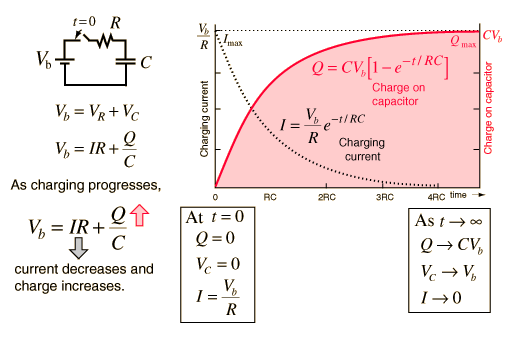
                        If I look at this:

                        Charging a Capacitor

                        I do not see anything specifically mentioning power consumed/translated in the resistor. The resistance, the capacitance, the current and the voltage determines the charge time of the capacitor. To me, so far so good.

                        Now, I have figured out as Aaron mentioned that the switching must work around the four quadrants of the sign wave. First quadrant, piece of cake--generator voltage is high, capacitor is zero, flip the switches and charge it through the load. The load needs to have low enough resistance and the capacitor needs to be sized properly to get it to charge here in stage one. Simple stuff.

                        In quadrants two and three, I think the switching pretty much stays idle or has a slight overlap into quadrants one and four. Mostly nothing to do here, move along.

                        Quadrant four is where it gets tricky. Best I can tell, you need to set the switches in such a way to flip/flop the capacitor so its polarity is reversed, but then... It gets hairy. Now you have to discharge the cap, through the load and back to the generator. Only problem is the generator is at peek voltage (minus, but still peek) at the beginning of quadrant four. So the cap isn't initially going to discharge at all, in fact, it may charge a little more momentarily if it didn't get completely charged in quadrant one.

                        Since what I'm trying to accomplish here in quadrant four is to give the generator a push and get it to motor, I'm not sure if I should dump the cap early or late. From looking at the scope shots...? I still can't really tell. I think I need to dump early, maybe clear back in quadrant three in order to fully empty the capacitor and be ready for the next cycle. I'm thinking dump at the start of quad-3 for an 1/8th cycle, then again an 1/8th into quad-4. If anyone can clarify this, I sure would appreciate it before I blow-up a bunch of very expensive semiconductors.

                        The whole trick to this gizmo from my un-seasoned background is to keep the electrical energy flowing. Look for high/low potentials and trigger switches accordingly, always moving the electricity through the load.
                        Last edited by Dog-One; 07-24-2014, 03:18 AM.

                        Comment


                        • This is a close up of the waves but I do not know what is what as far a what is called a quadrant.

                          This is 1 or 2 cycles not really for sure coming out of the transformer (standard isolation type)


                          Thanks Mike

                          Comment


                          • Scope Shot Analysis

                            Originally posted by BroMikey View Post
                            This is a close up of the waves but I do not know what is what as far a what is called a quadrant.

                            This is 1 or 2 cycles not really for sure coming out of the transformer (standard isolation type)
                            You got it Mike. Great pic to work from. I like to focus on the scope shot of the load since it sees every switching event.

                            The quadrants in your pic are in order 1-4, left to right. If we half these quadrants one more time and look at a single complete cycle (360 degrees) split into eight parts (each 45 degrees), I can really see where we need to do our switching.

                            The thing we need to keep in mind with the SERPS is it is highly load dependent for tuning purposes. Because of the capacitor RC constant, the load and capacitance has to be right, then the switching should work fine or can be tweaked slightly with a micro-controller to optimize output power versus reduction of back EMF on the generator. I have no idea if Paul used a micro-controller for the demo or not, but I would certainly recommend it.

                            Lastly, the switching... I have been designing what I call the Universal Electronic Switch that will do both AC and DC and is fully isolated from power and signal. Once I get that done, I'll be ready to do some testing. Oh BTW, if anyone wants to patent this switch... Prior art exists at OSE and will be filed at:
                            Defensive Publications

                            Just saying.
                            Attached Files
                            Last edited by Dog-One; 07-24-2014, 05:45 AM.

                            Comment


                            • Isolating Switching Circuit

                              Originally posted by Dog-One View Post
                              You got it Mike. Great pic to work from. I like to focus on the scope shot of the load since it sees every switching event.

                              The quadrants in your pic are in order 1-4, left to right. If we half these quadrants one more time and look at a single complete cycle (360 degrees) split into eight parts (each 45 degrees), I can really see where we need to do our switching.

                              The thing we need to keep in mind with the SERPS is it is highly load dependent for tuning purposes. Because of the capacitor RC constant, the load and capacitance has to be right, then the switching should work fine or can be tweaked slightly with a micro-controller to optimize output power versus reduction of back EMF on the generator. I have no idea if Paul used a micro-controller for the demo or not, but I would certainly recommend it.

                              Lastly, the switching... I have been designing what I call the Universal Electronic Switch that will do both AC and DC and is fully isolated from power and signal. Once I get that done, I'll be ready to do some testing. Oh BTW, if anyone wants to patent this switch... Prior art exists at OSE and will be filed at:
                              Defensive Publications

                              Just saying.
                              Bravo Dog-One

                              The picture does not completely reflect your diagram as you stated it is not done. Thank you for your kind words for the scope shot.

                              If we take this literally as shown in the picture, these pulses have many irregularities and so to perform a complex function like this would without doubt require some processing power, bare minimum.

                              So are you saying that the picture holds two complete cycles or is this one?

                              Mike

                              Comment


                              • Originally posted by BroMikey View Post
                                So are you saying that the picture holds two complete cycles or is this one?
                                That is a single cycle. Pretty sure.

                                AC waveforms : Basic Ac Theory

                                Comment

                                Working...
                                X