Announcement

Collapse
No announcement yet.

William F. Skinner - 1939 Gravity Power

Collapse
X
 
  • Filter
  • Time
  • Show
Clear All
new posts

  • William Skinner Gravity

    Hi Aaron,

    Regarding the 1200% report, I think that the commentator simply got it wrong. As you say, the claimed COP is 12 but that figure would only produce 1.5 HP, or around 1100 watts.
    The claim that it "could drive a generator to power a township of 3500", made me think that the COP must have been somewhat greater than that. A COP of 1200 would theoretically give each individual 3kw to play with, so I stuck with a 1200x power gain.

    I will post my videos on youtube as soon as I can edit them

    Comment


    • William Skinner - 1939 Gravity Power

      Hi,

      Thanks for your interest.
      I have uploaded some video clips to:

      https://www.youtube.com/watch?v=nYaN...ature=youtu.be

      Comment


      • There's one thing that I don't think anyone's touched on yet.

        Most of the replications so far are single sections of Mr. Skinner's machine. Goldpro is the only one who has built a double unit and if you look at his, you will see the point I am about to make.

        I believe the bottom tall weights on Mr. Skinner's machine are NOT free to fall on their own. In the original clip, you can see Mr. Skinner moving one slightly. But what you don't see is that the other 3 must also be moving because they are all mechanically linked together most likely with sprockets and chain to a central axle at the bottom of the machine. (actually if you look at around the 30 second mark you can see another arm moving as he moves the one)

        You can see in the video that opposite sets of weights are always 180 degrees out of phase. Or adjacent sets are always 90 degrees apart. If they weren't mechanically timed this way the unbalance would tear the machine apart.

        What that means is that the weights are either 'falling' in pairs or all at once with 2 falling to the outside and two falling to the inside, but not individually.

        Assuming this is the case, its possible at startup that it could take several seconds to overcome the inertia and get the bottom weights moving and synchronized with the top weights. I watched the video again and there really isn't a portion that shows it starting up where you can see the bottom weights as well.
        Last edited by purelyprimitives; 06-27-2014, 05:17 AM.

        Comment


        • Hi Dave Q

          Originally posted by Dave Q View Post
          ... uploaded some video clips to:

          https://www.youtube.com/watch?v=nYaNN1IBPwc
          Thank you for the concise and clean presentation in your video and the schematic in your posting http://www.energeticforum.com/258345-post236.html

          Comment


          • correction

            Originally posted by goldpro View Post
            Aaron,

            Thanks for the 90* explanation, that makes sense now.

            In the above paragraph you mention first clockwise then you say in the same counter clockwise direction. ? as usual I'm confused ?

            How about an explanation for this one:
            In the diagram from Dave he has this listed as his 2nd point:
            "As mass A is raised, then falls again by gravitational force every 180* of rotation"
            Does he means the weight actually raises when viewed from the side?

            thank you
            Tom
            Sorry, supposed to only be clockwise - I'll correct that.

            For me the jury is out on the upper weight raising and lowering.
            Sincerely,
            Aaron Murakami

            Books & Videos https://emediapress.com
            Conference http://energyscienceconference.com
            RPX & MWO http://vril.io

            Comment


            • lathe power

              Originally posted by purelyprimitives View Post
              In the newspaper article he does say that his lathe would normally require 2 HP.


              Its possible he was downplaying the number. However, the article does state that he 'estimates' the multiplication factor at 1200%. Someone who is able to conceive and execute a device of this complexity would seem to be someone who could 'estimate' something close to what it actually would be.

              Too bad we'll never know why he never patented this machine.
              My lathe is actually 9x20 and is only 3/4 HP for about 600 watts or so. Grizzly.com

              Maybe he did try to patent it and it got deep 6'd.
              Sincerely,
              Aaron Murakami

              Books & Videos https://emediapress.com
              Conference http://energyscienceconference.com
              RPX & MWO http://vril.io

              Comment


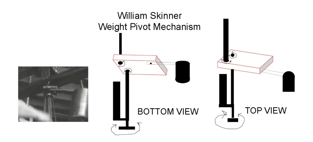
              • translation coupler geometrical relationship between lever, lower shaft and upper wt.

                Originally posted by gotoluc View Post
                Hi Aaron,

                when the topics first started I did my own investigation and wanted to do experiments based on what I was observing before going along with what was first shared.

                I posted the picture below at the OU topic on June 14th (some weeks after I had noticed this) if you look closely the upper levers position in the translation plate is not in line with the lower shaft.
                Noticing this I decided to offset mine as well. However, since I used a self alining pillow block as bearing on the translation plate for the lower shaft, I can adjust the lower shaft to infinite positions.

                Hope this clears your concern?
                Revisions may be needed?

                Luc


                Luc,

                It's like this - that's what I originally saw almost 2 years ago.

                The upper shaft is not in alignment with the top of the lower shaft. However, if the input lever is perfectly vertical, I believe it is in perfect alignment with the bottom of the lower shaft.

                Lower shaft and upper weight connection are separated by 90 degrees with the lever point at the middle of that L.

                Sincerely,
                Aaron Murakami

                Books & Videos https://emediapress.com
                Conference http://energyscienceconference.com
                RPX & MWO http://vril.io

                Comment


                • Originally posted by Dave Q View Post
                  Hi,

                  Thanks for your interest.
                  I have uploaded some video clips to:

                  https://www.youtube.com/watch?v=nYaN...ature=youtu.be
                  Very cool model Dave Q!

                  Comment


                  • 4 pole synergy?

                    Originally posted by purelyprimitives View Post
                    There's one thing that I don't think anyone's touched on yet.

                    Most of the replications so far are single sections of Mr. Skinner's machine. Goldpro is the only one who has built a double unit and if you look at his, you will see the point I am about to make.

                    I believe the bottom tall weights on Mr. Skinner's machine are NOT free to fall on their own. In the original clip, you can see Mr. Skinner moving one slightly. But what you don't see is that the other 3 must also be moving because they are all mechanically linked together most likely with sprockets and chain to a central axle at the bottom of the machine. (actually if you look at around the 30 second mark you can see another arm moving as he moves the one)

                    You can see in the video that opposite sets of weights are always 180 degrees out of phase. Or adjacent sets are always 90 degrees apart. If they weren't mechanically timed this way the unbalance would tear the machine apart.

                    What that means is that the weights are either 'falling' in pairs or all at once with 2 falling to the outside and two falling to the inside, but not individually.

                    Assuming this is the case, its possible at startup that it could take several seconds to overcome the inertia and get the bottom weights moving and synchronized with the top weights. I watched the video again and there really isn't a portion that shows it starting up where you can see the bottom weights as well.
                    That all has to be considered. The only thing I wrote about this in the past is that the "four pole" system was to stabilize it. With my single pole system up to speed even with the light weight aluminum lower weight, the inertial propulsion will move it across the floor.

                    Is there something additive or synergistic with a multi pole system that can't be had with one? We need to definitely find out. After we all have the lever input mechanism perfected for elliptical orbit - then its time to make the 4 pole system.
                    Sincerely,
                    Aaron Murakami

                    Books & Videos https://emediapress.com
                    Conference http://energyscienceconference.com
                    RPX & MWO http://vril.io

                    Comment


                    • Skinner output

                      Originally posted by Dave Q View Post
                      Hi Aaron,

                      Regarding the 1200% report, I think that the commentator simply got it wrong. As you say, the claimed COP is 12 but that figure would only produce 1.5 HP, or around 1100 watts.
                      The claim that it "could drive a generator to power a township of 3500", made me think that the COP must have been somewhat greater than that. A COP of 1200 would theoretically give each individual 3kw to play with, so I stuck with a 1200x power gain.

                      I will post my videos on youtube as soon as I can edit them
                      If his input is under 100 watts x 1200 times = 120,000 watts. 120,000 / 3500 = 34 watts per home. The 120,000 seems way more than his machine can product, and 34 seems too little. But in 1939, what was the average draw for a home in electricity? Average home might have just a couple lightbulbs and maybe a clock? Not sure.
                      Sincerely,
                      Aaron Murakami

                      Books & Videos https://emediapress.com
                      Conference http://energyscienceconference.com
                      RPX & MWO http://vril.io

                      Comment


                      • The Simple Solution

                        Hi All Replicators,

                        I treated this like a major breakdown at a local factory, where I have been sought out many times by engineers when the S**t hits the fan, even at 1am. Well here it is, and the most likely the method used by Skinner. The simplest, cheapest and the most elegant, a design solution an engineer in 1939 would have used. The exact materials and parts William possibly used, I still have on the drawing board.

                        Regards Arto

                        Comment


                        • Originally posted by hal.freeman View Post
                          Very cool model Dave Q!
                          Great work Dave!
                          very inspiring video!
                          You gotta love that Meccano !!!


                          Tom

                          Comment


                          • Originally posted by artoj View Post
                            Hi All Replicators,

                            I treated this like a major breakdown at a local factory, where I have been sought out many times by engineers when the S**t hits the fan, even at 1am. Well here it is, and the most likely the method used by Skinner. The simplest, cheapest and the most elegant, a design solution an engineer in 1939 would have used. The exact materials and parts William possibly used, I still have on the drawing board.

                            Regards Arto

                            Wow, very simple indeed.
                            That should be doable for every home shop engineer.
                            I see you show adjustment holes in the wheels so one can create whatever shape ellipse is needed or even turn the ellipse 90 degrees.
                            wheel with eye, closest to lever rod, determines width of wide part of ellipse.
                            wheel with L, farthest from lever rod, determines width of narrow part of ellipse.
                            great drawings!

                            thank you
                            Tom

                            Comment


                            • Hi Aaron,

                              Originally posted by Aaron View Post
                              That all has to be considered. The only thing I wrote about this in the past is that the "four pole" system was to stabilize it. With my single pole system up to speed even with the light weight aluminum lower weight, the inertial propulsion will move it across the floor.

                              Is there something additive or synergistic with a multi pole system that can't be had with one? We need to definitely find out. After we all have the lever input mechanism perfected for elliptical orbit - then its time to make the 4 pole system.
                              I think you are better off with one. At least then, you have some asymmetry and inertial propulsion as you say. The more I study Mr. Skinner's machine, it appears to be totally balanced and symmetrical which is not where you want to be.

                              For instance, we know that opposite sets of weights are constantly 180 degrees out of phase. If you were to measure two sinusoidal waveforms on a scope that were 180 degrees out of phase and hit the 'add' button, they would cancel each other out. So I would say that there is nothing 'additive' here. In fact, it would seem to resolve into being just a fancy flywheel. And we both know that there's no OU in a flywheel.

                              Comment


                              • Hi Aaron,

                                Originally posted by Aaron View Post
                                Sorry, supposed to only be clockwise - I'll correct that.

                                For me the jury is out on the upper weight raising and lowering.
                                If the upper weight is not raising and lowering, then, by extension the lower weight isn't either. And if the lower weight isn't, then there's no 'falling' to a new center of gravity. (This is what I now believe is happening)

                                It would seem that once the machine has reached a constant velocity, centripetal force would prohibit any motion other than a simple circular pattern (like a flywheel). Would you agree?

                                Charlie

                                Comment

                                Working...
                                X