Announcement

Collapse
No announcement yet.

William F. Skinner - 1939 Gravity Power

Collapse
X
 
  • Filter
  • Time
  • Show
Clear All
new posts

  • elliptical path

    Originally posted by gotoluc View Post
    I know it makes sense to think the levers are going in a circular motion when you consider the right and left levers are out. That's what I was thinking weeks back. But what if the right and left levers are going in and out and the front and back are going side to side?
    I hope you realize you're proving the point that Mike and I showed in diagrams.

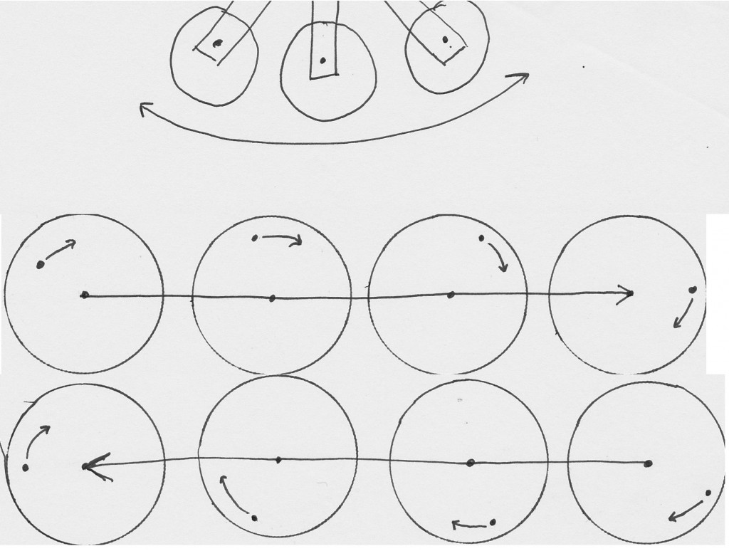
    If the top crossbar is only oscillating back and forth, how does the top of the rod exit the perimeter of the frame? If it wasn't for the little wheels/arms rotating on the end of the oscillating bar, the top of the rod would be fixed to a simple back and forth oscillation and would remain inside the perimeter of the frame.

    By the way, the claimed "linear" motion is actually a slight arc and not linear because the oscillating bar is on a piviot in the middle meaning the end of the oscillating bar is tracing an arc.

    At the end of the oscillating bar are little wheels or arm that rotates around and causes the top of the lever to exit the permieter of the frame as the full path that is traced is elliptical.
    Sincerely,
    Aaron Murakami

    Books & Videos https://emediapress.com
    Conference http://energyscienceconference.com
    RPX & MWO http://vril.io

    Comment


    • Input lever rotates in an elliptical path

      http://feelthevibe.com/free_energy/s...ticallever.zip 52.4mb - that is a video clip from the beginning of the original video showing the top mechanism.

      I have it zoomed in quite a bit, little blurry but the mechanism is very clear - you can see the oscillating cross bar going back and forth while the top of the lever rotates around a wheel/cam as shown below tracing an elliptical path as a matter of indisputable fact.

      Had this not been visible in the video, sure, debate it all you want, but since it is there plain as day, sorry to burst anyone's bubble that wants to keep perpetrating the misinformation about it going in only a linear or circular motion are completely wrong.

      The top of the input lever is doing 100% exactly as I have described from the beginning and diagrammed here:


      If nobody likes my aggressive attitude on this subject, too bad. Too much time and effort has been invested to show the truth and I will take a stand against blatantly false information being perpetrated about this machine. Like I said, it is not disputable because the evidence is right there in front of everyone's eyes who are intellectual honest enough to admit it.
      Sincerely,
      Aaron Murakami

      Books & Videos https://emediapress.com
      Conference http://energyscienceconference.com
      RPX & MWO http://vril.io

      Comment


      • Originally posted by iflewmyown View Post
        gotoluc,

        I have been building machines for over fifty years. Many times I use parts already in my shop or parts off of the last prototype. This requires more thinking and more labor, but less money. I am building a full size replica of this machine. It will function as Skinner's does, but not have exactly the same parts. The gears on top may have been old threading gears off of lathes.
        Garry
        Well Garry, I wish you luck since that's what it's going to take to get this device to work without one real working replication.
        I've been around these public research forums for over 8 years and built all kinds of things. This looked simple enough so I built an 8 foot single version (see my videos) but no free lunch from gravity yet.
        I know of others who built but don't share on the forums and it's the same for them.
        The bottom line is, if Mr. Skinner's device really worked then we don't have all the information. That's what I'm trying to let people know, real facts
        If anyone here knows it works then prove me wrong and show us your working device with P in - P out.

        Hopefully through replication attempts and tests someone may find something but this is starting to look like 99% of all the other topics that have gone by over the years. No real gain or information

        Luc
        Last edited by gotoluc; 07-08-2014, 10:57 PM.

        Comment


        • Originally posted by gotoluc View Post
          Hi William,

          I know it makes sense to think the levers are going in a circular motion when you consider the right and left levers are out. That's what I was thinking weeks back. But what if the right and left levers are going in and out and the front and back are going side to side?

          Luc
          One interesting thing I just now noticed in the photograph. It 'appears' that all 4 arms are pointing out.

          I realize that the machine is at rest here but I thought the 4 arms were tied together mechanically at the top and adjacent arms were always 90 degrees out of phase so that when one opposite set is furthest apart (pointing outward), the other set are closest together (pointing inward). But in the photograph, they are all pointing out??

          Can anyone reconcile this?

          Comment


          • Originally posted by purelyprimitives View Post
            One interesting thing I just now noticed in the photograph. It 'appears' that all 4 arms are pointing out.

            I realize that the machine is at rest here but I thought the 4 arms were tied together mechanically at the top and adjacent arms were always 90 degrees out of phase so that when one opposite set is furthest apart (pointing outward), the other set are closest together (pointing inward). But in the photograph, they are all pointing out??

            Can anyone reconcile this?
            Good observation on your part there purelyprimitives
            As far as I know the top mechanism is all tied together! how else could it stay in timming
            Also notice the bottom weights. They are not all the same, the side ones are in and front and back are out.

            Luc
            Last edited by gotoluc; 07-08-2014, 11:31 PM.

            Comment


            • OK, scratch that.....

              Its most likely an optical illusion and the arms are actually pointing inward at the top. Just looks weird....

              Comment


              • Originally posted by purelyprimitives View Post
                OK, scratch that.....

                Its most likely an optical illusion and the arms are actually pointing inward at the top. Just looks weird....
                No, I think you had it right!

                Luc

                Comment


                • Originally posted by gotoluc View Post
                  Good observation on your part there purelyprimitives. As far as I know they are all tied together!
                  Also notice the bottom weights. they are not all out, thew side ones are in and front and back are both out.

                  Luc
                  That's the way that I think we have all assumed it was. I just can't really tell from the photograph if the arms in the foreground and background are tilted in or out.

                  It would make sense that the weights would cause the tilt of the upper arm in the opposite direction. Based on the weights in the foreground, the attached upper arm should tilt in.

                  But like I said...just looks weird

                  Comment


                  • Originally posted by purelyprimitives View Post

                    But like I said...just looks weird
                    I agree, something looks weird.

                    Look at the lower left and right weights, they are in and their upper weight which is 90* forward has just pasted the frame... so why is their upper lever leaning out so much

                    Maybe something important here?

                    Luc

                    Comment


                    • Maybe the upper levers are mostly offset to the outside of the frame with a movement that's a straight line across (side to side) then half circle (outwards), so basically a half circle?

                      That would be an interesting twist!

                      Luc

                      Comment


                      • Have a look at this looped video I made back in May and posted at the OU forum topic.

                        Look only at the left side upper lever. You'll see the lever travels away from the side steel frame but when it comes back in it doesn't travel inwards as much as it travels outwards. You can't even see the very top of the lever pass the other side of the steel frame.

                        Link to video: http://www.overunity.com/14655/1939-...attach/138942/

                        I think this would support the half circle motion, would it not? ... or at least an elliptical that is offset to the outside of the frame.

                        Luc
                        Last edited by gotoluc; 07-09-2014, 01:12 AM.

                        Comment


                        • Hi Luc,

                          I think I downloaded that one when you first posted it and have referred to it often. Its a great clip.

                          Definitely something different about it. I wish we had a clearer and closer clip of its actual movement which would end the controversy

                          Comment


                          • the angle

                            Hi Luc, does it not look like that just due to the angle it was filmed at?
                            I am still trying different things, I think that the inputs, because there are 3, are all offset. Thats' 12 in total for a complete machine.
                            Top input, mid , bottom weight.
                            The centre of gravity from the top input is offset from the mid plate , which is offset from the output.
                            artv

                            Comment


                            • Originally posted by purelyprimitives View Post
                              Hi Luc,

                              I think I downloaded that one when you first posted it and have referred to it often. Its a great clip.

                              Definitely something different about it. I wish we had a clearer and closer clip of its actual movement which would end the controversy
                              Looking at the looped video (front lever) frame by frame and I counted about 12 to 13 frames each half cycle (side to side). So I don't think it can be equal if it was a half circle since the straight movement would be a shorter distance then the half circle. So looks more like an elliptical movement with an offset to the outside of the frame.

                              Luc
                              Last edited by gotoluc; 07-09-2014, 01:56 AM.

                              Comment


                              • Originally posted by shylo View Post
                                Hi Luc, does it not look like that just due to the angle it was filmed at?
                                I am still trying different things, I think that the inputs, because there are 3, are all offset. Thats' 12 in total for a complete machine.
                                Top input, mid , bottom weight.
                                The centre of gravity from the top input is offset from the mid plate , which is offset from the output.
                                artv
                                I can't tell for sure but something looks strange

                                Your experiments sound interesting,

                                All the best

                                Luc
                                Last edited by gotoluc; 07-09-2014, 01:59 AM.

                                Comment

                                Working...
                                X