Announcement

Collapse
No announcement yet.

William F. Skinner - 1939 Gravity Power

Collapse
X
 
  • Filter
  • Time
  • Show
Clear All
new posts

  • Geometry

    Armandino, let me recount my impressions of the geometry of the original Skinner machine. To me, it appears that the top of the lower shaft moves in a circle of about 4--5 inches.
    I believe that the bottom of the upper shaft moves in a circle or ellipse that is the same size. From the bottom of the upper shaft to the gimbal is about 1 foot. It is about 4 feet to the top of the upper shaft. The circle (or ellipse) that is described by the top of the upper shaft is dictated by this ratio. The top of upper shaft will move in a circle that is 4 times the diameter of the circle travelled by the bottom of the upper shaft.
    I can't say if the top of the upper shaft runs in a circle or an ellipse. But, I believe that the ratio between the part below the gimbal and part above the gimbal is an important aspect.

    The original vid shows a (almost) side view. If you watch the 4 shafts, the amplitude of movement appears to be close to equal. Are 2 of the gimbals in side view while 2 of the gimbals are in end view? I can't say.
    The lower shaft pivots / rotates at it's lowest point. The upper shaft rotates at a mid-point (not in the middle, naturally). The upper shaft uses leverage to move the weight,,, the lower shaft does not.
    Comment


    • Originally posted by Danny B View Post
      Armandino, let me recount my impressions of the geometry of the original Skinner machine. To me, it appears that the top of the lower shaft moves in a circle of about 4--5 inches.
      I believe that the bottom of the upper shaft moves in a circle or ellipse that is the same size. From the bottom of the upper shaft to the gimbal is about 1 foot. It is about 4 feet to the top of the upper shaft. The circle (or ellipse) that is described by the top of the upper shaft is dictated by this ratio. The top of upper shaft will move in a circle that is 4 times the diameter of the circle travelled by the bottom of the upper shaft.
      I can't say if the top of the upper shaft runs in a circle or an ellipse. But, I believe that the ratio between the part below the gimbal and part above the gimbal is an important aspect.

      The original vid shows a (almost) side view. If you watch the 4 shafts, the amplitude of movement appears to be close to equal. Are 2 of the gimbals in side view while 2 of the gimbals are in end view? I can't say.
      The lower shaft pivots / rotates at it's lowest point. The upper shaft rotates at a mid-point (not in the middle, naturally). The upper shaft uses leverage to move the weight,,, the lower shaft does not.
      Hello,
      I entered fully into cotruttiva phase of the mechanical system after thinking a lot and seen very often the original movie Skinner. After a year of reflection, I determined what could be, in my opinion, the dimensional aspects of everything that is part of the mechanism. I admit, it is very complex, requires competence and high notions of quantum physics.
      *despite the many interpretations of the forum friends questioning everything is debatable making, sometimes, the path to the very rough truth, I came to my conslusioni and I realized what you see in the movie and much more you still do not I filmed. I would like to recall that the distance from the upper pivot (primary drive) to the wedge point made with constant velocity joint (self-derived) is important to determine how much power you want to dale LEVER. I will remember that my comments are from tests performed and so many changes. The top spins the bottom through a top of intersection with the plate. rotating the lever down is possible only if the lower weight ENTERS PHASE SYNCHRONIZED with the rotation of the upper lever. this movement is conditioned by the inclined axis distance from the center of gravity, from the upper weight, from brazzio which supports the lower weight, and the amount by weight of the same, from the speed of rotation of the upper lever and the amplitude that is running in output from the constant-velocity joint. certainly it is a little complicated, but with practice you solve problems. It is what I try to do, I hope good.:Saluti:

      Comment


      • replica skinner machine

        Originally posted by mksboysal View Post
        Hi guys,
        The machine that are being discussed here I built it, it took me around four months to come to this completion, not finished yet. Enjoy the pictures. Frame size is 5 ft by 5 ft and the height is around 7 + ft. The lower weight is 340 lbs and the upper weight is around 75 lbs. As you can see the upper weight it's totally adjustable, you can slide back and forth if you want to. The driver motor is a 3 ph 1/8HP with a 56:1 gear ratio planetary gear it is controlled with 1/4 HP VFD drive. When I turn this thing on it's scary to stay close by! So I stand back 5,6 ft away when that 340 lbs rotates at 33 rpm or little higher you have to respect the "force in motion" under no load prime mover motor consumes 80 to 90 watts, the output power is still being tested!!! During the operation the frame sways a little but I have plans to make it firmer by installing cross braces all around the frame. Come along tool is temporarily hold the lower weight and does a good job with it. 90 decree weight lowers the input power close to 25 to 30 % anyway if you have a ? or comment drop me a line. If some of you need help? I maybe be available to help you design yours.
        Hello,
        Now I've seen pictures of your creation. finally another person that after reflection, builds a machine. if I may, I must make you see that is missing the top formed by the lever part, necessary to multiply the force of the motor and the load it must suffer the engine. as well as the structure was built in my opinion will not stand for a long time, it will break. You should be securely fixed to the wall otherwise be walking around the room or smashes. not seen robust support angles and are concerned about your health. as well as think about the utility of the machinery, you should pay more attention to your skin. the fear that you've had is legitimate.
        I may worthwhile I invite you to watch movies mei, maybe you can be useful.
        Do not stop, I think that we are few to try.

        Comment


        • http://i8.photobucket.com/albums/a28...pskjnqxl14.jpg

          Comment


          • input method?

            That looks like a nice solid build.

            How are you going to drive the input?
            Sincerely,
            Aaron Murakami

            Books & Videos https://emediapress.com
            Conference http://energyscienceconference.com
            RPX & MWO http://vril.io

            Comment


            • The rod is 193 lbs. The connectors are 1 inch aluminum and can be disconnected at both ends. The axle is tube, 1.75 O.D. and 1.25 I.D. The plywood with the hole is temporary to guide the shaft until it has more pieces. I took the rod off to continue without the humongous weight. The uprights are 12 ft. tall. The base plates are 1/4 inch. The lower bearing housing is 4 inch bar with 2 very large bearings in it. 3206B double row, angular contact. Below the bearing holder I have a 1/2 X 6 in. drive plate bolted to the axle. It has mounting holes for the drive pulley.
              I will probably use a Gilmer belt.
              The next step is the translation plate. Both the upper and lower axles are mounted in that plate. The upper is fixed. The lower floats. I'm guessing that the 2 axles are about 2.5 inches apart. Does anybody have any different ideas?

              The bearing for the top of the lower axle is; http://www.precisiontaperedrollerbea...motorcycle.jpg
              I had planned to use the same style bearing for the pivot on the upper axle instead of the gimbal. BUT, I'm wondering if the width-to-length bias of the gimbal is necessary to get the correct movement. ??????

              On the Terawatt device, my contention is that both wheels rotate at the same rpm. This would have one of them constantly accelerating and decelerating because they are locked together magnetically. If the upper rod of the Skinner device runs in an elliptic, it too would be changing velocity constantly.

              I can make the translation plate but, I can't actually install it anywhere until I have the gimbal. Any ideas on a gimbal vs a bearing?

              EDIT, "How are you going to drive the input? " ,,,, TBD!
              Last edited by Danny B; 06-30-2016, 01:04 AM. Reason: incomplete

              Comment


              • Gimbal vr roller or ball bearings

                Hi Danny, I have been trying various bearings and have concluded the ball bearings are far less capable of of handling the objective tilting of the bearing under load. I believe the gimbal is the best because it only requires each of the two bearing surfaces to accomplish one objective movement at a time. unlike the ball or roller bearing. That being said; The roller bearing surface is superior to the ball bearing because it does not object to the lateral movement of the bearing in the race surface by design. With the ball bearing the surface however having a concave race the bearing movement sliding at one direction and rolling in the other is highly objectionable, so you can see the roller bearing is the superior for this application, that is if you choose bearings rather than the gimbal. One last thing about the vertical weight on the bottom bearing, I am going to be using a stationery thrust roller bearing on a CV joint to carry all the weight. Like the hub in a car with 2 bearings and tapered races.

                My model is going to be small, maybe 4-5 feet. I may make some metal gimbals

                Edit:
                if you simply take a pencil, make a dot on paper, hold the point of the pencil on the dot, rotate the pencil round and round and observe the top of the eraser parallel to the paper you will have no up and down movement.
                On the contrary if you tilt the pencil 1/2 of a degree off of the vertical you will notice the up and down variation.
                If you don't believe me take a megaphone or any cone that is in relatively good condition and put the small end on the paper and tilt it off of vertical you will see plainly that this is the critical and only thing that will make your machine go up and down.

                This is probably the most important thing about your build that most people cant figure out how to solve. When I get it figured out I will share the solution.
                Last edited by h2ocommuter; 07-03-2016, 01:47 PM. Reason: Confusion about the up and down movement

                Comment


                • The Problem AND the Solution

                  Originally posted by h2ocommuter View Post
                  Edit:

                  if you simply take a pencil, make a dot on paper, hold the point of the pencil on the dot, rotate the pencil round and round and observe the top of the eraser parallel to the paper you will have no up and down movement.

                  On the contrary if you tilt the pencil 1/2 of a degree off of the vertical you will notice the up and down variation.

                  If you don't believe me take a megaphone or any cone that is in relatively good condition and put the small end on the paper and tilt it off of vertical you will see plainly that this is the critical and only thing that will make your machine go up and down.

                  This is probably the most important thing about your build that most people cant figure out how to solve. When I get it figured out I will share the solution.
                  I've already told you all many times that in your example, the eraser doesn't change height with a circular input.

                  I've also already provided the solution over and over, which is why the elliptical input is necessary because that DOES make the weight change height. It can be done with Skinner's elliptical method as I've shown in my videos or it can be done by taking a bicycle wheel and tilting it with the input lever in the wheel - tilting the wheel causes an elliptical input, which changes the height of the weight. It is highest at the narrow end of the ellipse and lowest as the far ends of the ellipse.

                  Without changing height, the machine doesn't regauge itself or reset a new potential difference between 2 different heights and misses out on utilizing gravitational potential as an input energy course into the machine - its really common sense.
                  Sincerely,
                  Aaron Murakami

                  Books & Videos https://emediapress.com
                  Conference http://energyscienceconference.com
                  RPX & MWO http://vril.io

                  Comment


                  • Distance inequitities with off-center allignment

                    Originally posted by Aaron View Post
                    I've already told you all many times that in your example, the eraser doesn't change height with a circular input.

                    I've also already provided the solution over and over, which is why the elliptical input is necessary because that DOES make the weight change height. It can be done with Skinner's elliptical method as I've shown in my videos or it can be done by taking a bicycle wheel and tilting it with the input lever in the wheel - tilting the wheel causes an elliptical input, which changes the height of the weight. It is highest at the narrow end of the ellipse and lowest as the far ends of the ellipse.

                    Without changing height, the machine doesn't regauge itself or reset a new potential difference between 2 different heights and misses out on utilizing gravitational potential as an input energy course into the machine - its really common sense.
                    Please watch the video first.
                    Without any cause you build a case against math. I will not belabor the insinuation That Simple math has no part in this gravity machine. I have reduced the math to a visual example. please don't flagrantly discard this logic and example. I regard you and your efforts with this forum highly, I just can't stand the insinuation that William Skinners device moved up and down. If you have any visual proof. of this as you may like to show us all when the machine is working. I see no slide components on Williams' machine that would suggest any up and down movement.

                    The minimum of 1/2" would be plenty of proof I would love to see the transition coupler, or the up and down movement of any bearing or slide component that is there. I am sorry if I have missed this in any way.

                    However hyperbole is not acceptable it is always discarded. That is common sense
                    https://www.youtube.com/edit?o=U&video_id=ufFbtK9hZOY

                    If you choose not to respectfully engage with me I will reluctantly concede your forum.

                    Comment


                    • elliptical input = secondary always falling

                      Originally posted by h2ocommuter View Post
                      Please watch the video first.
                      Without any cause you build a case against math. I will not belabor the insinuation That Simple math has no part in this gravity machine. I have reduced the math to a visual example. please don't flagrantly discard this logic and example. I regard you and your efforts with this forum highly, I just can't stand the insinuation that William Skinners device moved up and down. If you have any visual proof. of this as you may like to show us all when the machine is working. I see no slide components on Williams' machine that would suggest any up and down movement.

                      The minimum of 1/2" would be plenty of proof I would love to see the transition coupler, or the up and down movement of any bearing or slide component that is there. I am sorry if I have missed this in any way.

                      However hyperbole is not acceptable it is always discarded. That is common sense
                      https://www.youtube.com/edit?o=U&video_id=ufFbtK9hZOY

                      If you choose not to respectfully engage with me I will reluctantly concede your forum.
                      Skinner's machine has an elliptical input - because this is a fact based on the visual evidence of the machine itself, that means the level that the TOP of the lower lower weight changes height. The elliptical input is obvious from this observation: https://www.youtube.com/watch?v=lA9wHJsFzm4 and is explained in more detail here: https://youtu.be/JolNozy8UEY?t=34m50s

                      This is the simplest elliptical input I can come up with: https://www.youtube.com/watch?v=IbMUrY5MynA

                      It does not mean that the entire weight moves up and down and there is a difference. It is the level of the top of the weight that changes while the bottom stays at the same pivot point.

                      Take your pencil example and move it in a circle, the level at which the eraser is at does not change height.

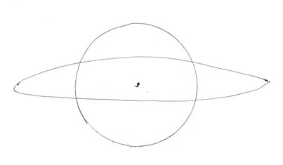
                      Take the same pencil and rotate it in an elliptical path, the height at which the eraser is at changes height - at the narrow end of the ellipse, the eraser is at the lowest height and at towards the center of the ellipse, the eraser will be at the highest.


                      Draw a picture like the above and stick your pencil lead on the dot in the center.

                      Rotate the eraser so it follows the circular path - the level that the eraser is at will not change and it will stay at the exact same level.

                      Rotate the eraser so it follows the elliptical path, the level that the eraser is at changes height.

                      The ellipse is exaggerated in the picture above to simply demonstrate the point and in Skinner's machine, the ellipse is not that exaggerated, but is just enough to get the top of the weight to change its height while the bottom of the weight stays where it is just like the pencil lead stays where it is.

                      For one, the lower weight turns freely around the shaft and is disconnected from it - no matter where you rotate the lower shaft or how, the weight will be "always falling" to the inside incline of the shaft.

                      For two, the weight is "always falling" when it is rotated in an elliptical path - when it gets towards the wide part of the ellipse, the top of the weight is at the highest and then it will fall, using gravity to help accelerate it towards the narrow end of the ellipse where it is the lowest. Then with the translation plate mechanism, it will whip back in the opposite direction without bucking against anything using the momentum to carry it back to its "highest" position at the wide part of the ellipse and the momentum carries it with the assistance of gravitational input back towards the narrow end of the ellipse at the opposite end and this continues to repeat. This is the entire point of why it is called "Gravity Power". Using a circular input prevents this added gravitational potential from contributing.
                      Sincerely,
                      Aaron Murakami

                      Books & Videos https://emediapress.com
                      Conference http://energyscienceconference.com
                      RPX & MWO http://vril.io

                      Comment


                      • top of lower weight changes height without moving up and down

                        I looked at your video, you misunderstood what I meant and my previous post should clarify that - I never said the entire weight is moving up and down because it doesn't - just the level of the top of the lower weight changes height if rotated in an ellipse, which is not possible with a circular input. I hope that clarifies what I'm talking about.
                        Sincerely,
                        Aaron Murakami

                        Books & Videos https://emediapress.com
                        Conference http://energyscienceconference.com
                        RPX & MWO http://vril.io

                        Comment


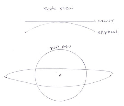
                        • elliptical vs circular side and top views

                          For further clarification, here is a side view added similar to your video where you can see the top of the weight will change height in an elliptical orbit.

                          Sincerely,
                          Aaron Murakami

                          Books & Videos https://emediapress.com
                          Conference http://energyscienceconference.com
                          RPX & MWO http://vril.io

                          Comment


                          • Wobble plate

                            Damn, I missed a bunch of posts. I don't seem to get any notification. Everyone is aware that Tesla was very big on building and not particularly interested in theoretical mumbo jumbo.
                            http://i8.photobucket.com/albums/a28...psjjgaepbe.jpg

                            http://i8.photobucket.com/albums/a28...psrbueve5k.jpg
                            The center to center distance is 3 inches,,, best guess.
                            Next, comes the gimbal.

                            Comment


                            • will work for dimensions

                              I figure 10 inches from the gimbal to the wobble plate. Does anyone have different ideas? I have the material for the gimbal. Just need to do the machining.

                              Comment


                              • pics

                                http://i8.photobucket.com/albums/a28...pscsdgoiwx.jpg

                                http://i8.photobucket.com/albums/a28...psqg2akoru.jpg

                                http://i8.photobucket.com/albums/a28...psqmlkxn69.jpg
                                Last edited by Danny B; 07-17-2016, 08:24 PM. Reason: more pic

                                Comment

                                Working...
                                X