Announcement

Collapse
No announcement yet.

William F. Skinner - 1939 Gravity Power

Collapse
X
 
  • Filter
  • Time
  • Show
Clear All
new posts

  • tuning

    Originally posted by goldpro View Post
    wow! That's a very impressive build!

    I noticed that starting at about the 53 second mark of the video the
    upper weight farthest from the camera doesn't turn at a constant speed.
    It seems to speed up and slow down.
    I'm not sure about the others.
    the two to the right of the camera seem to turn at the same speed.

    What horsepower is the motor?

    I hope you can do what Peter suggested.

    good Luck.

    Tom
    hello, thank you always for your prezioni suggestions. I spoke about a failing rotor is now correct. the abnormal rotation was caused by a bearing that not having friction, was fionfare weight over the position derived from the lower weight. while the other three use a tube inside another tube that having friction reach the desired position by 90 ° on the vertical axis. for synchronizing the lower weights I stuck to converging pair of rotors and after I stretched as far as possible the chain. use an induction motor 220v 180w. with reduction gear 10: 1 while I used a bicycle transmission input which currently runs everything at 45 rpm. I'm going to use a mechanical variator axis to the engine that will allow me to adjust the turns a little at a time.

    Comment


    • Offset pivot

      That's quite an expensive machine that you have built. AND, quite dangerous. I certainly wouldn't go to 100 rpm.,,, especially with just one connection and a chain on the lower weight.
      Earlier, I wrote; "The upper pivot point for the drive could be offset from the center of the gimbal." Apparently, you have offset the lower pivot point rather than the upper. (5 cm.)
      Was there any reason that you moved the pivot of the lower weight rather than the upper weight?
      I'm doing load testing now. It takes about 30 watts, DC to rotate 150 kg. at 60 rpm.
      The reason that I ask about you moving the lower pivot as opposed to the upper pivot is; all 4 lower weights MUST be locked together to do actual drive work. All 4 weights MUST be synchronized to keep the machine from shaking apart. If you lock them together, how is any one weight going to free-fall on the downhill stroke?

      On my build, The arm that drives the upper shaft only positions the shaft. It does not drive it in rotation. The upper shaft is free to rotate or not. After my initial load testing, I'll move the upper pivot off-center. I expect the rotation of the shaft to "retard" on the uphill and "advance" on the downhill.
      It remains to be see just how much of this variable speed can be imposed on the lower weights if the 4 shafts are locked together.

      Comment


      • Originally posted by Danny B View Post
        That's quite an expensive machine that you have built. AND, quite dangerous. I certainly wouldn't go to 100 rpm.,,, especially with just one connection and a chain on the lower weight.
        Earlier, I wrote; "The upper pivot point for the drive could be offset from the center of the gimbal." Apparently, you have offset the lower pivot point rather than the upper. (5 cm.)
        Was there any reason that you moved the pivot of the lower weight rather than the upper weight?
        I'm doing load testing now. It takes about 30 watts, DC to rotate 150 kg. at 60 rpm.
        The reason that I ask about you moving the lower pivot as opposed to the upper pivot is; all 4 lower weights MUST be locked together to do actual drive work. All 4 weights MUST be synchronized to keep the machine from shaking apart. If you lock them together, how is any one weight going to free-fall on the downhill stroke?

        On my build, The arm that drives the upper shaft only positions the shaft. It does not drive it in rotation. The upper shaft is free to rotate or not. After my initial load testing, I'll move the upper pivot off-center. I expect the rotation of the shaft to "retard" on the uphill and "advance" on the downhill.
        It remains to be see just how much of this variable speed can be imposed on the lower weights if the 4 shafts are locked together.
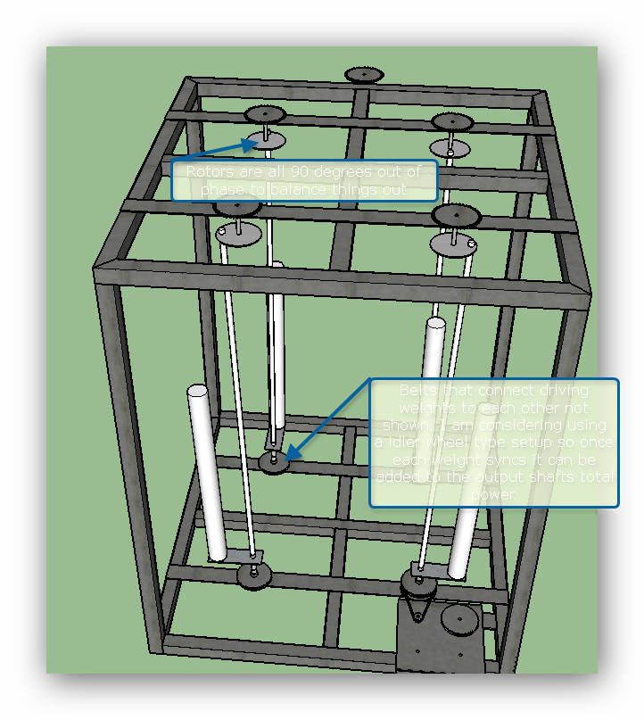
        Hello, I moved the vertical axis from the bottom in opposite configuration and in pairs. in a state of rest all weights are forced to position itself at the same time in the lower part of the rotation. and they are in the opposite position every 90 ° of rotation only canceling the negative effects of the centrifugal force on the bearing structure. when one of the weights reaches the lower part, the other are synchronized down in the lower part. as if it were a single weight equal to the sum of all of them. I will post a motion video startup. I am convinced that it is better to see the movements that explain how. I am convinced that could be equal to the displacement of the pivot center in the upper, and is much simpler to realize. In these photos I made the final drive with PTO.I also installed a bike motor 24v 250w which will avoid me to push with your feet the weight for avviale the mechanism. when I stop feeding the engine becomes the generator, which with a manual rotation, give me 30v, AC.
        Attached Files

        Comment


        • Originally posted by armandino View Post
          Hello, I moved the vertical axis from the bottom in opposite configuration and in pairs. in a state of rest all weights are forced to position itself at the same time in the lower part of the rotation. and they are in the opposite position every 90 ° of rotation only canceling the negative effects of the centrifugal force on the bearing structure. when one of the weights reaches the lower part, the other are synchronized down in the lower part. as if it were a single weight equal to the sum of all of them. I will post a motion video startup. I am convinced that it is better to see the movements that explain how. I am convinced that could be equal to the displacement of the pivot center in the upper, and is much simpler to realize. In these photos I made the final drive with PTO.I also installed a bike motor 24v 250w which will avoid me to push with your feet the weight for avviale the mechanism. when I stop feeding the engine becomes the generator, which with a manual rotation, give me 30v, AC.
          Hello, I wish in these drawings illustrate the processed for the timing of the lower weights. Also the upper levers have the same timing, but remember that the independent rotation from that of the lower weights.
          Attached Files

          Comment


          • Armandino, That is a very impressive build. It was very astute to offset the weights so that would act as one mass. There is one problem though. According to your doc that you posted, you have paired the weights adjacent Not opposite. Skinner has paired, synchronized weights that are diagonally opposed. This aligns the considerable mass transfer over the center of the machine.

            Comment


            • Basic machine

              https://drive.google.com/file/d/0B-r...nl&ts=58045b94
              On Youtube; https://www.youtube.com/watch?v=T3LmBjtNzE8
              Last edited by Danny B; 11-03-2016, 03:37 AM. Reason: Moooooare info

              Comment


              • Skinner machine design concept

                I have been studying the Skinner gravity machine for a few months and been doing some testing and I believe I have come up with a design that would work but I just have to collect the materials to build it in a small scale to test the concept. If anyone could take a look at my design and let me know if they think it would work and if not then what is wrong with my assumptions.
                Attached Files

                Comment


                • Scale up the gravity motor

                  Bump !
                  I understand what Skinner was trying to do. He appears to have had limited finance. The weights are hollow. All the weights are "clocked" so that they don't collide. If there were a "pumping action", it would have to be done with 2 weights moving in at the same time that 2 weights were moving out.
                  Locking the 4 shafts together would have to be done with either gears or chains. They didn't have cog belts at the time. Locking the lower shafts together means that any pumping would have to be done to all 4 at once. Otherwise, the effect would be cancelled.

                  If there were a pumping action, it should be apparent by watching the flat-belt. I don't see it. Also, any oscillation of speed would cause problems with using the lathe. I don't see any need for pumping action. Nor do I see any evidence of it.
                  The machine is straightforward. Leverage is the critical factor. All the output depends on the angle and length of the lower arm and the amount of weight on it.
                  Skinner spent 14 years working out his ideas. There might very well be a way to improve it but, it works like it is. Best to copy his design theory though, not his build. I understand how to build the "quad" machine. There is nothing tricky or critical about it. The machine is easy to scale-up. Just keep the angles the same.
                  Skinner used a PTO to drive his stuff. It shouldn't be too difficult to put a big diameter rotor like a wind-gen under the base and drive it directly. A homopolar motor could be used also. Lots of possibilities.

                  If anybody wants to take my machine and use it for development, you're welcome to take it. Since it isn't a balanced quad, it must be attached to a building.

                  Comment


                  • yes, I'm tired, never give up

                    Hello Danny,
                    It is a pleasure to find yourself. I, like you, I have not ceased to harass on the subject of the machine and its optimal functioning. You have to admit that we seek a highly desirable result in the world. Many scientists have deep thinking brain, sending him into a tailspin. The physical laws of this world prevent stubborn to even get small results. At the end of both larovo, money flying with the wind, hammering on his fingers, burned motors, you bang your head against a solid and impenetrable wall. I do not feel a normal and reasonable person. this my diversity gives me the strength to go on in this perverse game to grab the "miracle machine" that the whole world tries to achieve. often I give in to the evidence of my ignorance unbridgeable. other days I wake up with a "brilliant idea" that brings me in the midst of levers, mechanisms, motors, chains, weights, ellipses, acceleration .... and resume playing. is playing. This is the real desire that triggers all the springs of my brain. ensure contituità the game. who knows, maybe irrational reasoning could come to light, one day, the good solution to the problems that afflict people and find the "holy grail" of perpetual motion.
                    *I not stopped the construction of the machine. every other day I get a built in Poland generator specifically for my needs: 150rpm - 3 kW, 220V, 50Hz, confirming that ....... the dream continues.http://www.energeticforum.com/images/smilies/wall.gif

                    Comment


                    • Stop the squeak

                      Danny I can really appreciate your work.

                      The squeak is not indicative of such good work. the amp draw tells me something is not true. It "the squeak" happens always at the same point. The top shaft is pointing left, in the picture, the transmission coupler is pointing to the back right-hand quadrant, and the Lower shaft is pointing to the right.
                      the shaft without the motor gearing connected would tend to make me think the mechanism would come to rest with the levers in approximately this position.

                      I would love to take it home to do more developments with but I am fresh out of space. big offer for the right person.

                      Comment


                      • When I run into data limit problems I make trip to the local library where they have free wifi and using the download plugin that Aaron mentioned in my firefox and download the video there then I can watch it as many times as I want ast home. If you have any broadband free internet access that is what I would recommend you do also.
                        Last edited by zipster1967; 02-06-2017, 01:19 AM.

                        Comment


                        • Originally posted by velacreations View Post
                          I don't care about "closing the loop" as much as making something that can provide useful work.

                          Heck, I've got a 10 watt power source, can I have 120 watts in return, please?

                          anyone got instructions on how to build one and run your house?


                          I know this is an old 'thread' but IF you are still reading here, I have EXACTLY what you are asking for!
                          However, due to regular and systematic SABOTAGE on this Forum, I will only reveal this info to you personally (or perhaps others who are GENUINELY interested) since I am NOT interested in ANY form of argument!!
                          You can contact me at lbanki at bigpond dot com (FIX the email address)
                          Cheers,
                          Les Banki

                          Comment


                          • yet another walter skinner replication

                            dooo dooo dooooo dooo, dooo dooo dooooo doo

                            *insert ufo imogee

                            Hello ESM'rs,

                            im currently reading through this thread,

                            love gravity machines and pendulums,

                            always have,

                            I AM Determined too work a replica of some youtube videos i am inspired by,
                            and i plan too post the images and experiences on the forum, - hoping peeps are going too help me out,. - im currently lathe'ing some mdf drive pulleys, and will post the progessess tomorrow,, - the machine is days away from completion and testing.

                            PEACE>YO
                            Attached Files

                            Comment


                            • last night it struck me that my math was a little wrong... and came back to check some progress....

                              rohndoe had a pretty good demo...
                              https://www.youtube.com/watch?v=gTWwp5qUY3U

                              the longer the vertical shaft, the less work is used (L2a/L1*Mg) to raise the weights so they can fall, but the real work is resulting as torque on the shaft, (L2*Mg). removing Mg as a common factor from both leaves L2 (length of the arm), L2a (length of the arm + a little for the offset of the horizontal from the bottom), L1 (Length of the arm from the horizontal to the top).

                              L2 is constant so whatever length arm you have determines the base multiplier of torque.
                              L1 increasing decreases the work to raise the weight.

                              Oh, but it's the sin of the angle only that gets applied to the torque so a longer arm has a lesser angle (unless the top rotation is increased in diamter, which is doable I suppose; limited by the angle of ... well no, I guess a gear system on two hemispheres could be made such that even 90 degrees can result in good torque transfer. (100% gravity to torque translation) (or really just 2 45 degree gears since it doesn't have to pivot)

                              I guess 1.0 translation of mass to torque would be having the drive bar horizontal (attached image)


                              you don't gain RPM directly - the red (output generator/transmission) could be a gearbox to leverage it. The lower the output load, the lower the weight will be up to a maximum.... would need to be some sort of limit.

                              The outside ring would have to be fixed to the center part and rotate together... (lazy suzan plate in the center? )

                              That design is of course less horizontal space efficient but gains vertical stacking efficiency (somewhat).

                              (classic john device model, with a mostly vertical shaft, but then output torque only gains the sin(theta) torque, where theta is < 5 degrees, whereas the above is 90 degrees which sin(90) = 1.0 )


                              Some possible builds of a flat device....
                              The top is like a peice of plywood or something with a hole cut in it in the center for the gear drive, and a hole for the arm to go through, can then mount the drive arm down to that....
                              the second is the same sort of idea but maybe a bicycle wheel with a few spokes removed so the drive gear can get through...would have to keep the bar from moving in and out and keep it meshed against the center gear...


                              But this sort of arrangement simplifies the math some; should be easier to prove that the linear force required on the outside of the drive is less than the torque force you can get out for basically any mass > 1 on the mass-arm. and based on how much greater you can then consider moving it back to a more vertical drive

                              But then also the load needs to be a greater force than the input in order to require any gain from the pivoting mass. The mass would hang vertically and basically be a 1:1 transfer from the input drive to the output drive, then as the output requires more load, the weight would raise and compensate, and the input would gain at a rate of L2/L1 ( if L2(the mass arm) is shorter than L1 (the drive arm) the required force will then be that fraction of force required, and you'll start to note a greater output.

                              The skinner device would mostly be leveraging its inertial to drive a lathe, and probably only a very very tiny shift in the weights would be required. Full load would be the drive shaft ahead of the mass by 90 degrees. (even in Rohnjoe's video because there's no real load, the mass is only slightly lagged from the drive, only the slight force required to overcome the friction on the bottom would lag the weight).
                              Attached Files

                              Comment


                              • Centrifugal force tests I made

                                I am very intreagued by Skinner's machine and have read all the fine work you all have done. I was very curious about centrifugal force and did the following tests that gave me hope.
                                Skinner 1939 gravity machine centrifugal force tests and hope

                                In this case I used a seesaw movement and not an oval.

                                And now I'd like to make a similar setup to test the input and output
                                of the Skinner principles.

                                More than anything right now the world needs a better energy source
                                along with some serious peace....

                                Norman

                                Comment

                                Working...
                                X