Gravity Power Paper 2
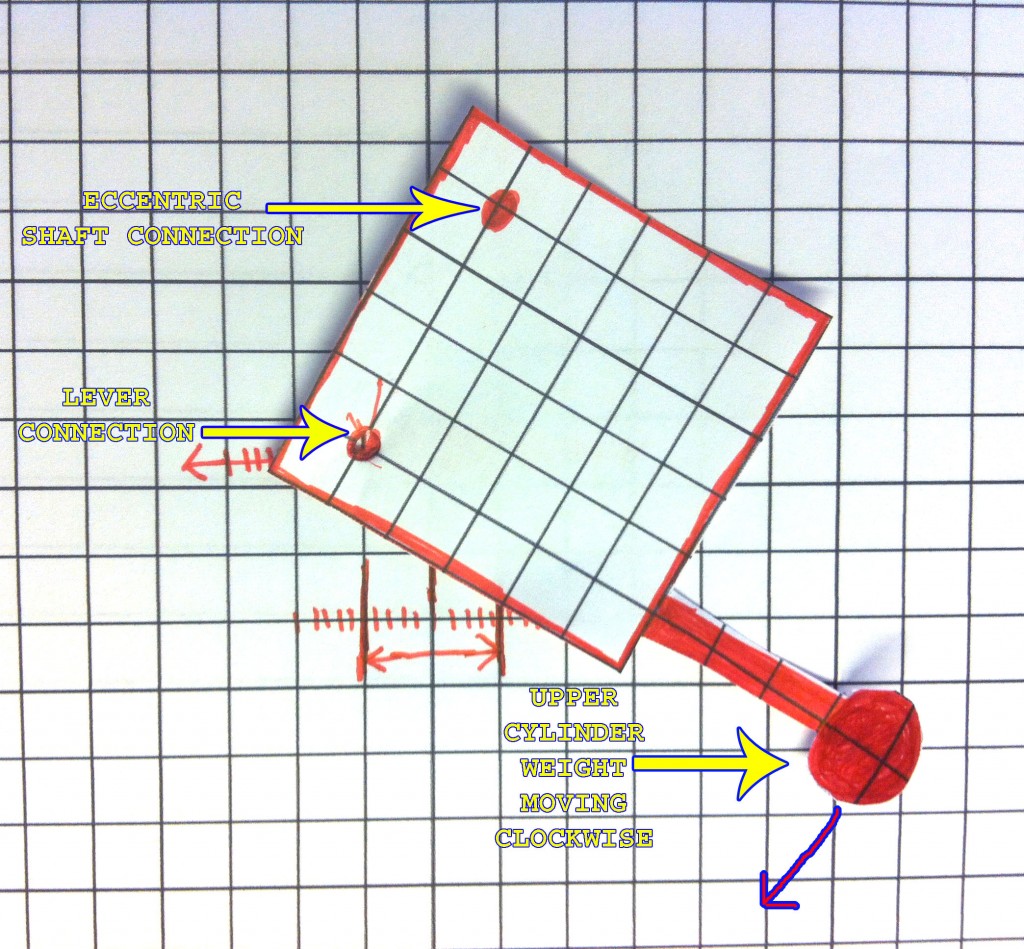
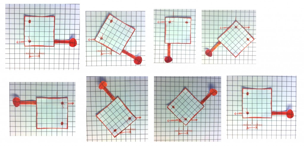
Look at the sequence of the steps with the weight rotating clockwise in relation to the pivot point from the lever that simply moves back and forth.
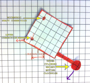
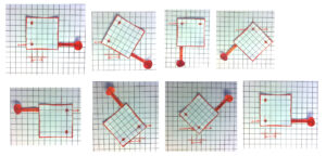
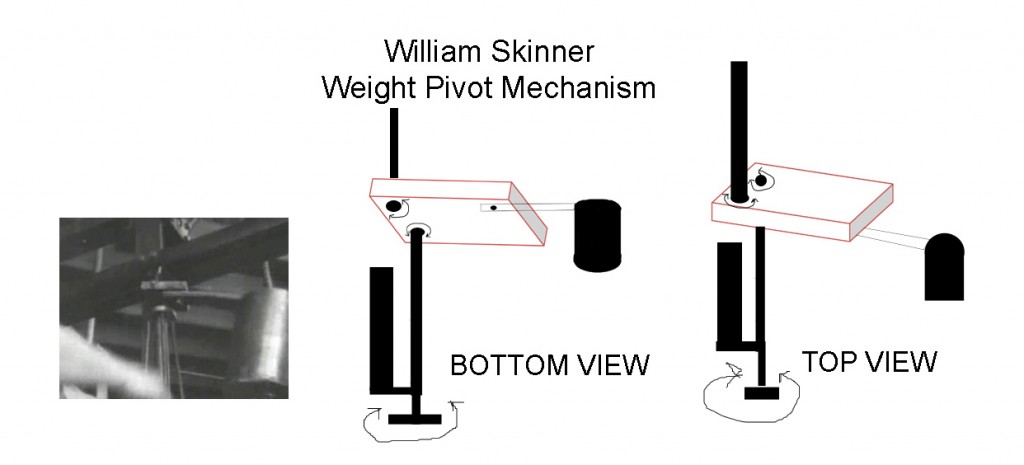
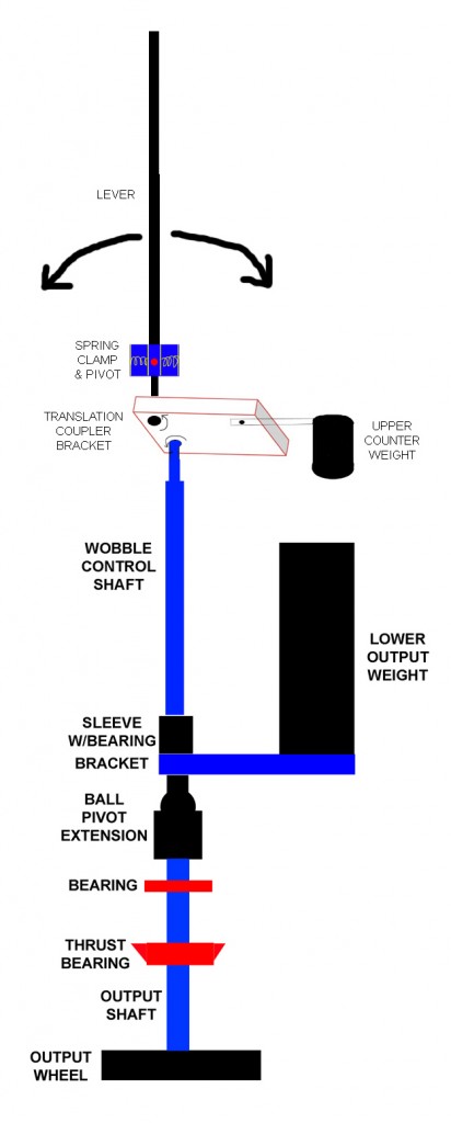
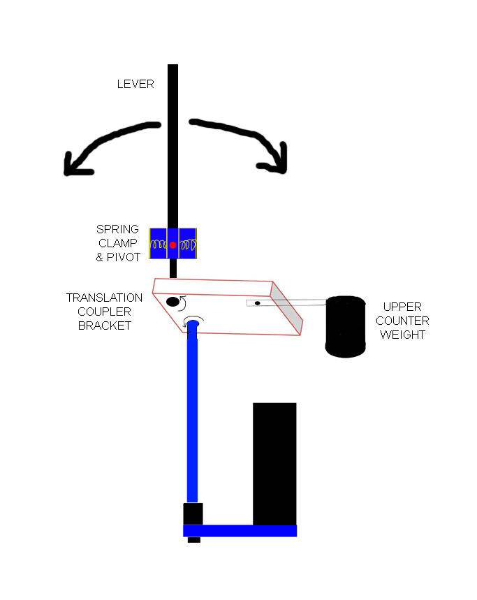
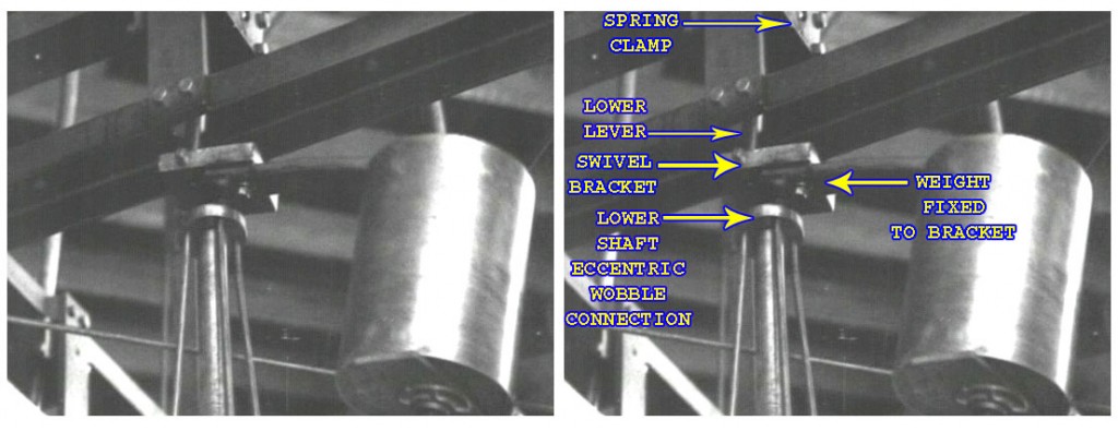
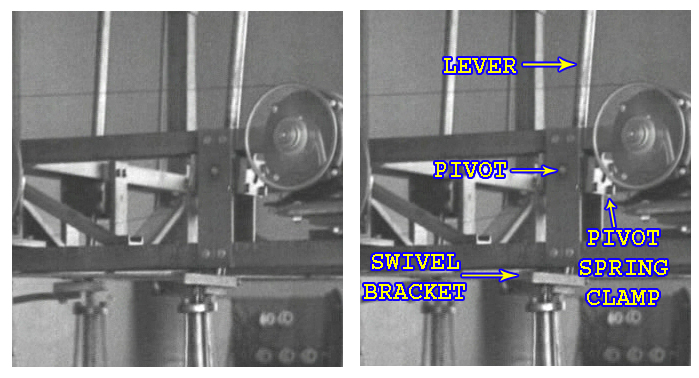
Steps 1~7 are the entire sequence and the 8th step is a repeat of the first to show the complete cycle. The below pictures shows you what each part of the swivel bracket is.
Step 1 – The lever point is to the far left and the weight is to the far right with momentum swinging it in the clockwise direction.
Step 2 – The lever point is still in the left position and the weight is still swinging around.
Step 3 – The lever point is in the same position but the weight is still swinging around.
Step 4 – At this point, the lever point is able to move towards the right direction. When pushing on the bracket from that corner in the right direction, it is in unison with the weight already moving in the clockwise direction. They reinforce each other.
Step 5 – The lever point is at the far right and the weight is at the far left.
Step 6 – The lever point is at the far right and the weight is still swinging around.
Step 7 – As soon as the bracket is situated so that the lever point can move in the opposite direction and move in unison with the weight, it moves towards the left.
Step 8 – Back to position 1.
Again, the momentum of this upper cylindrical weight carries it in a clockwise direction and this mutually reinforces the back and forth movement of the lever’s action. They are in a positive feedback cycle with each other. This translates back and forth motion to rotational movement and the rotational movement assists the lever’s back and forth movement.
As you can see, the weight is not moving around a fixed point of axis, it is moves to the left and right. It is rotating around an axis that is to the left half the time and then to the right half the time. That is the two input pulses from the lever per full rotation.
From the same sequence of steps, we can see that the point at which the lower eccentric shaft connects, it too has a none fixed orbit. Not only does the upper part of the lower shaft wobble around in a circle, it is an orbit that also has a moving axis point.
6. The next part of the trick of the system besides the Swivel Bracket mechanism is the lower weight fixed to the bottom axis of the lower shaft.
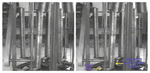
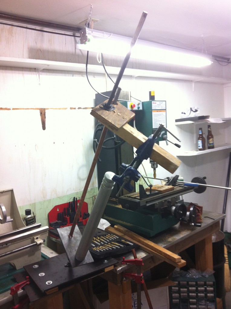
The long cylindrical weight is on a bracket that is fixed to the bottom of the lower eccentric shaft. That appears to be the only place that the lower weight is connected. It is also slightly angled outwards. With this weight, it will always try to position itself to be on the inside of the inclined shaft.
As the upper cylinder weight fixed to the Swivel Bracket rotates, the eccentric shaft is connected to the opposite corner of the bracket. The upper weight leads the bracket around and this causes the eccentric orbit of the lower shaft to constantly follow it. Therefore, since the eccentric shaft’s position is constantly changing, the lower eccentric shaft weight is constantly moving to a new center of gravity.
As long as the upper weight continues to circle, the lower weight will continue to follow.
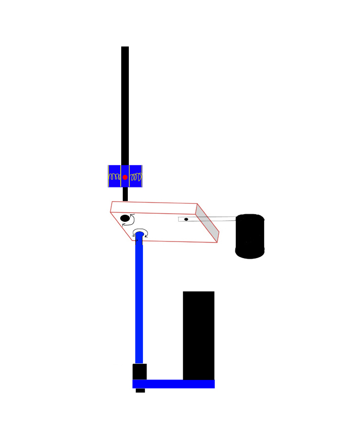
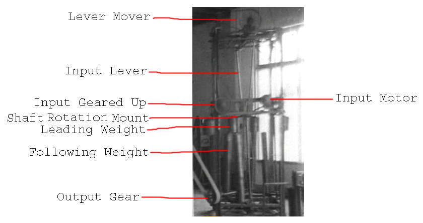
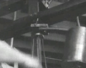
The eccentric shaft has a fixed axis at the bottom and is connected by some means of gears, belts, etc… to a central wheel what turns the long shaft at the bottom left of the above picture. That is the output shaft and it’s power is taken from the large belt that goes to running the lathe.
To summarize, we are leveraging leverage.
We use a very small amount of energy to rock the lever back and forth. With enough length, it takes very little energy to move its connection to the bracket back and forth. The lever’s movement in conjunction with the upper cylinder weight self-reinforces each other’s movements. The back and forth movement is reinforced by the eccentric movement of the weight. And the weight’s eccentric movement is reinforced by the very small input from the back and forth movement of the lever.
As the Swivel Bracket rotates from the above stated action, the lower eccentric shaft’s connection is put on an eccentric orbit, which constantly follows the upper weight’s orbit. This causes the lower eccentric shaft’s weight to follow the upper weight producing torque at the bottom of it’s shaft that can be tapped by an output shaft.
Lever movement > moves bracket > upper weight reinforces lever’s movement > causes eccentric shaft orbit causing a moving center of gravity > lower weight constantly moves to the moving center of gravity causing mechanical shaft power at the bottom.
No laws of physics are violated. It is an open non-equilibrium thermodynamic system that is open to free gravitational potential. This gravitational potential is able to constantly act as a source of work energy on the lower weight because of the constant shifting of the center of gravity that the lower weight is seeking.
From a little input on the lever, we are able to massively amplify the amount of work we can take from the output by the described mechanism. This appears to be the highest COP (coefficient of performance) mechanical amplifier that has ever been revealed to the public.
Look at the sequence of the steps with the weight rotating clockwise in relation to the pivot point from the lever that simply moves back and forth.


Steps 1~7 are the entire sequence and the 8th step is a repeat of the first to show the complete cycle. The below pictures shows you what each part of the swivel bracket is.
Step 1 – The lever point is to the far left and the weight is to the far right with momentum swinging it in the clockwise direction.
Step 2 – The lever point is still in the left position and the weight is still swinging around.
Step 3 – The lever point is in the same position but the weight is still swinging around.
Step 4 – At this point, the lever point is able to move towards the right direction. When pushing on the bracket from that corner in the right direction, it is in unison with the weight already moving in the clockwise direction. They reinforce each other.
Step 5 – The lever point is at the far right and the weight is at the far left.
Step 6 – The lever point is at the far right and the weight is still swinging around.
Step 7 – As soon as the bracket is situated so that the lever point can move in the opposite direction and move in unison with the weight, it moves towards the left.
Step 8 – Back to position 1.
Again, the momentum of this upper cylindrical weight carries it in a clockwise direction and this mutually reinforces the back and forth movement of the lever’s action. They are in a positive feedback cycle with each other. This translates back and forth motion to rotational movement and the rotational movement assists the lever’s back and forth movement.
As you can see, the weight is not moving around a fixed point of axis, it is moves to the left and right. It is rotating around an axis that is to the left half the time and then to the right half the time. That is the two input pulses from the lever per full rotation.
From the same sequence of steps, we can see that the point at which the lower eccentric shaft connects, it too has a none fixed orbit. Not only does the upper part of the lower shaft wobble around in a circle, it is an orbit that also has a moving axis point.
6. The next part of the trick of the system besides the Swivel Bracket mechanism is the lower weight fixed to the bottom axis of the lower shaft.

The long cylindrical weight is on a bracket that is fixed to the bottom of the lower eccentric shaft. That appears to be the only place that the lower weight is connected. It is also slightly angled outwards. With this weight, it will always try to position itself to be on the inside of the inclined shaft.
As the upper cylinder weight fixed to the Swivel Bracket rotates, the eccentric shaft is connected to the opposite corner of the bracket. The upper weight leads the bracket around and this causes the eccentric orbit of the lower shaft to constantly follow it. Therefore, since the eccentric shaft’s position is constantly changing, the lower eccentric shaft weight is constantly moving to a new center of gravity.
As long as the upper weight continues to circle, the lower weight will continue to follow.
The eccentric shaft has a fixed axis at the bottom and is connected by some means of gears, belts, etc… to a central wheel what turns the long shaft at the bottom left of the above picture. That is the output shaft and it’s power is taken from the large belt that goes to running the lathe.
To summarize, we are leveraging leverage.
We use a very small amount of energy to rock the lever back and forth. With enough length, it takes very little energy to move its connection to the bracket back and forth. The lever’s movement in conjunction with the upper cylinder weight self-reinforces each other’s movements. The back and forth movement is reinforced by the eccentric movement of the weight. And the weight’s eccentric movement is reinforced by the very small input from the back and forth movement of the lever.
As the Swivel Bracket rotates from the above stated action, the lower eccentric shaft’s connection is put on an eccentric orbit, which constantly follows the upper weight’s orbit. This causes the lower eccentric shaft’s weight to follow the upper weight producing torque at the bottom of it’s shaft that can be tapped by an output shaft.
Lever movement > moves bracket > upper weight reinforces lever’s movement > causes eccentric shaft orbit causing a moving center of gravity > lower weight constantly moves to the moving center of gravity causing mechanical shaft power at the bottom.
No laws of physics are violated. It is an open non-equilibrium thermodynamic system that is open to free gravitational potential. This gravitational potential is able to constantly act as a source of work energy on the lower weight because of the constant shifting of the center of gravity that the lower weight is seeking.
From a little input on the lever, we are able to massively amplify the amount of work we can take from the output by the described mechanism. This appears to be the highest COP (coefficient of performance) mechanical amplifier that has ever been revealed to the public.
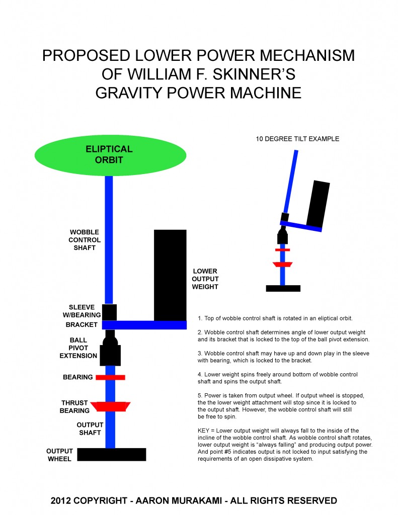
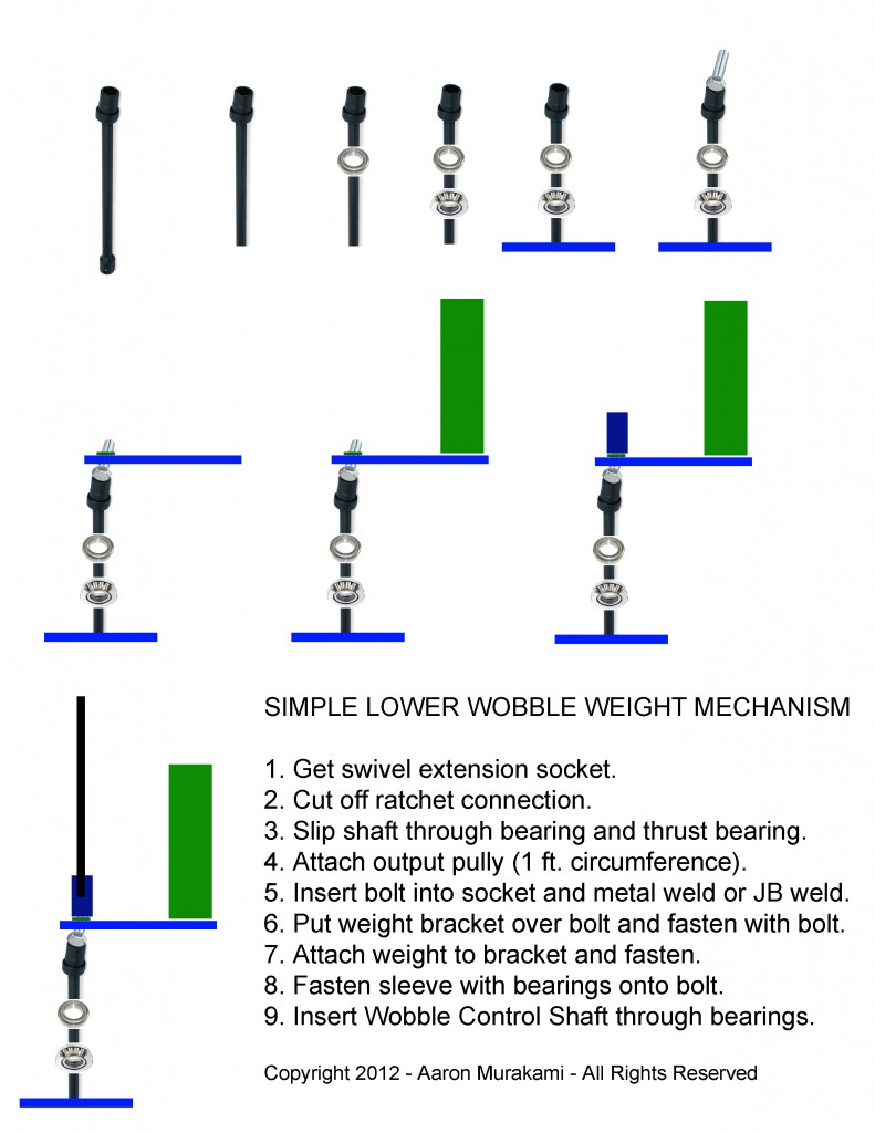

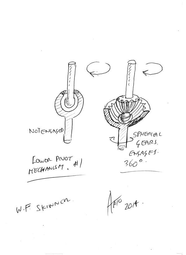
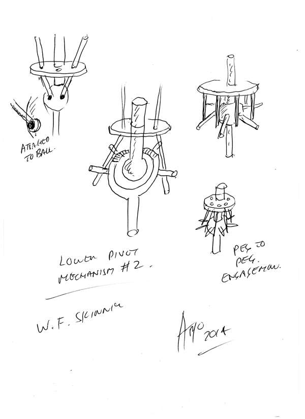
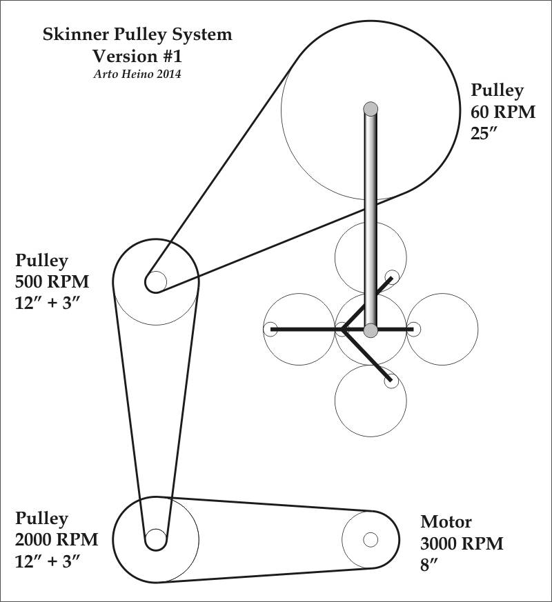
 I'm talking about the bottom final joint to the power takeoff


Comment