Announcement

Collapse
No announcement yet.

William F. Skinner - 1939 Gravity Power

Collapse
X
 
  • Filter
  • Time
  • Show
Clear All
new posts

  • You can get an elliptical motion with ONLY A LINEAR DRIVE. If there is any side to side movement allowed by the looseness of the connections, the ROTATING WEIGHTS will move it from side to side while the linear drive moves it back and forth. As long as the drive stroke is longer than the allowed side to side movement you will have an elliptical rotation. Perhaps THIS is what we are seeing in the video???

    I have been working on a linear drive mechanism using a 18 volt saws all that is connected to two vertical shafts and I see this kind of elliptical movement in my build. The two vertical shafts are at the North South position, and both move away from center at the same time. In addition, I have figured out how to couple this to two more shafts in the East West position and these two shafts would move toward center at the same time as the North /South pair are moving AWAY from center. I wanted this alternating movement to keep the unit in some kind of balance so it will not rip itself apart, and this has been the TOTAL focus of my build. ALSO, two moving away and two moving in help to balance the force necessary to drive the system. I can also vary the length of the linear movement from the 2" available directly from the movement of the saws all, to as long a stroke as I want. Now that I have this part figured out, I am ready to go on to the the rest of the build. I have been working on THIS ONE PART of the build since this thread was first posted because I felt it was necessary to figure out how to move all FOUR vertical shafts with one linear movement, and I wanted two to go out while two moved in. Sometimes I just have to beat my head against the wall for a while before I can figure something out, and you all have moved way past me.

    IF anyone is interested, I would be happy to share this, but you need to know I developed it as a LINEAR DRIVE and the ELLIPTICAL movement is more a result of the "looseness" of the design than anything I have designed on purpose. I felt like if I could get the linear movement in all the directions I needed, I could figure out how to modify it into an ellipse.

    Aaron,

    I share this because I believe working together is the ONLY way we can figure these things out, and I don't think we should overlook ANY possibility. I would hate to see anyone driven from this thread because of a difference of opinion. The proof is in the pudding. I think we all need to build according to our own opinion and see what we come up with. May the best man win.

    Dave
    “Advances are made by answering questions. Discoveries are made by questioning answers.”
    —Bernhard Haisch, Astrophysicist

    Comment


    • The great counter-logical (superficially so) mystery of gravity is that mass' field is convergent and centripetal, however its accumulation is spatial and radial.

      Mass has spatial volume but a counterspatial field.

      Mass, like dielectricity 'folds' space (just the opposite of the insanity of Einstein who reifies space AS a THING, AS the 'medium', it is just the inverse)


      Dielectricity terminates at great scale stellar powers into the creation of mass. Likewise mass/gravity has near identical properties to dielectrcity, it has torque, and while spatially accumulative (as mass) its field is convergent and centripetal.

      Centrifugal inertia generated in mass which naturally has a centripetal field creates a spatial disequilibrium and the 'odd' phenomena seen in gyroscopes and this device.

      We may indeed be about to create overunity by inverting the oppositional inertial and convergent mass/dielectric fields of matter.


      centrifugal spins on matter which is field convergent is like imposing counterspatial fields on polarized magnetic fields.

      Which the dielectric inertial plane of ALL magnets DOES, which is why the midpoint of any magnet HAS NO MAGNETISM.

      Same reason why if you were in a bubble at the center of the earth, there would be no gravity at all.


      Weight, like fields are both location (in the field) specific, and medium specific/dependent.


      Alll fields necessarily has a null/0 point fulcrum where max density thresholds are permeated and the field is superseded in its attributional effects.

      the boundary of maximum field density is also the boundary, necessarily, of 0 or null-point field transcendence.
      Last edited by TheoriaApophasis; 07-06-2014, 07:30 AM.

      Comment


      • Were my Eyes Deceiving me?

        I really do appreciate the lively communications. a couple of weeks ago when I found this thread I searched through and noticed so much sincere information and this great Project to replicate. I saw some hi-def. pictures of what looked like the TOP of Skinner's machine "up close". Last week when I went back to examine them I could not find them. anyone got any ideas?

        Here is my replication and buildup....

        Upper Gimble Motor Assy - YouTube

        Comment


        • Originally posted by h2ocommuter View Post
          ...
          I saw some hi-def. pictures of what looked like the TOP of Skinner's machine "up close". Last week when I went back to examine them I could not find them. anyone got any ideas?
          ...
          Hi,

          Those pictures you are looking for were uploded by gotoluc at the ou forum first, see this link:
          1939 Gravity Power - multiply power by 1200%

          Perhaps you could ask gotoluc whether he also uploaded those pictures on this forum too, unfortunately I cannot recall whether he did or did not upload them here.
          Anyway, the pictures are available at the above link.

          Gyula

          Comment


          • upper drive

            Hi Turion, Would it be possible to show a pic or video ?
            To Dave Q , I watched your video but, with the two units you didn't have the lower shafts and output hooked up. Or did I miss another somewhere.

            Like Turion is saying linear drive wants to go eliptical so it has to be designed to allow for the back and forth to be able to move side to side at the same time.

            The upper shaft does not rotate it gives the appearance of rotation. Attach a threaded rod to the outside of a wheel, spin the wheel ,the rod doesn't rotate ,the wheel does. If the rod is attached at the other end to another plate , the other plate rotates , but not the rod .

            Dave Q please keep testing and posting it helps to see different ideas.
            I don't believe anybody is trying to mis inform People just see and explain differently.
            artv

            Comment


            • Originally posted by Dave Q View Post
              Aaron,

              I'm really sorry to read that you suspect deliberate misinformation is being posted.

              I've been a compulsive inventor since childhood. At age 75, my motivation in the field of "free energy" is to break our current dependence on oil and utility companies.

              I simply built what I could see, and my small models worked perfectly.
              On Friday I was really excited to find that driving two properly timed reciprocating drives uses less power than driving one.

              I can see that I should have worded my posts more diplomatically.
              I've tried to be thorough and to demonstrate principles.

              Sorry if I have hurt anyone's feelings.

              This will be my "last post" on the subject.

              Best regards.
              Sadly Dave made the same mistake that I did assuming that this is a forum where the free and open exchange of ideas is welcomed.

              It's actually more like a church where only the One True Viewpoint is to be venerated. Anyone espousing heresy is immediately burned at the stake with the crime of subverting the masses with their sinful alternate viewpoint.

              Comment


              • what happened? was someone censored?

                Comment


                • I have no pictures available at the moment. I have a new shop at my place in Northern California where I am working on this, and my home in San Jose that I am on the way to now is "under construction" as we get ready to sell it. I won't be back up to the new place for a couple weeks. Sorry about that. But I did sketch it out and will attach that. It is a very simple design. The motor is mounted to move vertically. There are lots of things that can affect how well this works, and that is what I have been messing with The length of the arm between where it is attached to the motor and the pivot point. The length of the arm between the pivot point and connection to the vertical shaft. HOW it is attached to the vertical shaft. I showed ONE idea for that that will actually work WITHOUT the "L" shaped arm between the motor connection and the vertical shaft, but the connector plates would have to be flipped over to get the leverage in the right direction. This is probably all just confusing everyone, so I will post the picture and shut up.

                  Dave
                  Last edited by Turion; 09-03-2014, 09:55 PM.
                  “Advances are made by answering questions. Discoveries are made by questioning answers.”
                  —Bernhard Haisch, Astrophysicist

                  Comment


                  • I thought at first it was also a linear drive with the levers rigid and moving back and forth. I later saw that there was an additional pivot.


                    Then someone further corrected me by showing a model of the gimbal.. . https://www.youtube.com/watch?v=u1dvSINRylk
                    And right at the beginning of the black and white Skinner video you can see that the rods are actually attached to gears that travel in a circle, and the rod entirely pierces the gimbal to go down to the square plate....

                    artoj made a drawing... which I see was posted here a couple pages back, and a better more schematic drawing also...
                    here's the rough one...


                    which made me try and find where he got the information.... and finally saw (barely, and only a couple split seconds) the top drive mechanism. Youtube has watch options that you can watch at 0.25x (1/4) speed. I spent a while watching the beginning at that speed, and it's not linear, or elliptical but rather circular entirely. I thought that the rod was actually sepearted to drive the rocking mechanism at the top back and forth(marked in green in first picture), but then saw the secondary pivot (marked in red in first picture) and thought it was a seperate rod entirely anchored there (since the separation between the two pivots was quite large) which could imply an elliptical path... but in reality, the bottom moves in sync with the top, and the top travels in a circle, being mounted at the edge of a circular gear. (I would have included a picture, but it's so blurry that only the motion can really be seen, so a single static image does it no justice)

                    My cheesey simulations using Space Engineers.
                    https://www.youtube.com/watch?v=PvBFqjvWfjo
                    https://www.youtube.com/watch?v=GdlT35EZqd0

                    Was mostly about the gimbal; I had some better models, but they had misplaced points... and because I only have single axis pivots available (no knuckle/CV joint sort of thing) I have to turn the machine up to a very high drive. (in the second one, the scale of power is in kN and MN (kilonewton, megnewton) but the mass blocks they are driving are in units of 50,000kg... it's actually a very large scale) the rotors on the motor have SOME give to them, but takes a lot of force to get it to overcome just the twist at the top of the axel attached to the rotor.

                    -------------
                    Flywheel. There's a guy with TheJohnDevice(.com). He starts good, with a single mass at the end of a rod...
                    but then he starts to add more mass but with a balance character; this just increases the flywheel character of this device, and really the only accelerating mass is still only the initial 2.2 pounds or something.
                    https://www.youtube.com/watch?v=9-KVo4lxHgE (intro, good start)
                    by part 4 https://www.youtube.com/watch?v=J0AsR126bSI he has a lot of balanced mass which just moves the COG to the center, and adds to the flywheel character.

                    This shows the ideal arrangement off mass, so when the axle is moved, the weight is lifted slightly, and then starts to fall... then because of the continuous rotation of the top of the axle, the weight is always in a state to falll.... somewhat - at a constant RPM the mass will actually always run ahead and, and fall back down slightly...


                    Forces based on a linear drive, your maximum force is at the ends initially, lifting the entire mass of the weight quickly, and least at the end; positive force input requirements shown in red, and feedback in blue... The pink circle should actually be a continuous line of light blue and light pink segments...


                    ----
                    Hmm embedded image didn't work...

                    Edits: replaced internal links to attached images with external sources... why can't I just use the attachments on this message as embedded images?
                    Attached Files
                    Last edited by d3x0r; 07-06-2014, 06:19 PM.

                    Comment


                    • stop the disinformation

                      Originally posted by purelyprimitives View Post
                      Sadly Dave made the same mistake that I did assuming that this is a forum where the free and open exchange of ideas is welcomed.

                      It's actually more like a church where only the One True Viewpoint is to be venerated. Anyone espousing heresy is immediately burned at the stake with the crime of subverting the masses with their sinful alternate viewpoint.
                      You are obviously trying to push your own agenda to make it look this way. My posts are in simple English, go back and read my post(s) because you're missing something.

                      You keep pushing claims that are blatantly false and you refuse to answer simple questions - how does having a 4 pole system change the mechanics of how the lower weight rotates around it's shaft? You keep claiming flywheel but can't justify your claims. Not asking you to answer anymore because you obviously don't want to take part in disproving your own claims about the Skinner machine being a flywheel.

                      When someone makes claims and someone calls them on it and asks very specific questions, the simplest reason for being evasive is because of some other agenda that has nothing to do with understanding the machine. This is what you have demonstrated.

                      My posts are alluding to a handful of trouble makers in another forum who keep pushing their "circular" arguments and keep calling people names.
                      Sincerely,
                      Aaron Murakami

                      Books & Videos https://emediapress.com
                      Conference http://energyscienceconference.com
                      RPX & MWO http://vril.io

                      Comment


                      • nobody is censored

                        Originally posted by velacreations View Post
                        what happened? was someone censored?
                        No, but this is what purelyprimative would want you to believe for some reason.

                        I made a post about certain people pushing obviously false information to throw people off. There is what there is and then what people turn it into. Dave Q thought I was talking about him. Purelyprimative can't answer one very simple question when I confront him about his claims, that is highly suspicious. My main issue is with the troublemakers in another forum who are completely destroying it for new people in there by outright lying while calling a few people names.

                        This forum is for open discussion, that's the point. But if someone is making a claim about something, they are also opening themselves up to being challenged on it - that comes with the territory. Instead of answering my very simple question, pp whines about it and claims this is a church where only one viewpoint is welcome. Wow, I never heard that one before. That is his attempt to spin this out of context. Someone makes a claim - they should be equally open to justifying it. If they don't want to answer questions, then they have a double standard.
                        Sincerely,
                        Aaron Murakami

                        Books & Videos https://emediapress.com
                        Conference http://energyscienceconference.com
                        RPX & MWO http://vril.io

                        Comment


                        • lever is moving in an elliptical orbit

                          Originally posted by d3x0r View Post
                          And right at the beginning of the black and white Skinner video you can see that the rods are actually attached to gears that travel in a circle, and the rod entirely pierces the gimbal to go down to the square plate....

                          which made me try and find where he got the information.... and finally saw (barely, and only a couple split seconds) the top drive mechanism. Youtube has watch options that you can watch at 0.25x (1/4) speed. I spent a while watching the beginning at that speed, and it's not linear, or elliptical but rather circular entirely. (MY NOTE - ONLY CIRCULAR IN ITS OWN LOCAL FRAME OF REFERENCE EXCLUDING THE FACT THAT THE CIRCLE IS MOVING BACK AND FORTH IN SPACE)

                          but in reality, the bottom moves in sync with the top, and the top travels in a circle, being mounted at the edge of a circular gear. (I would have included a picture, but it's so blurry that only the motion can really be seen, so a single static image does it no justice)

                          Edits: replaced internal links to attached images with external sources... why can't I just use the attachments on this message as embedded images?
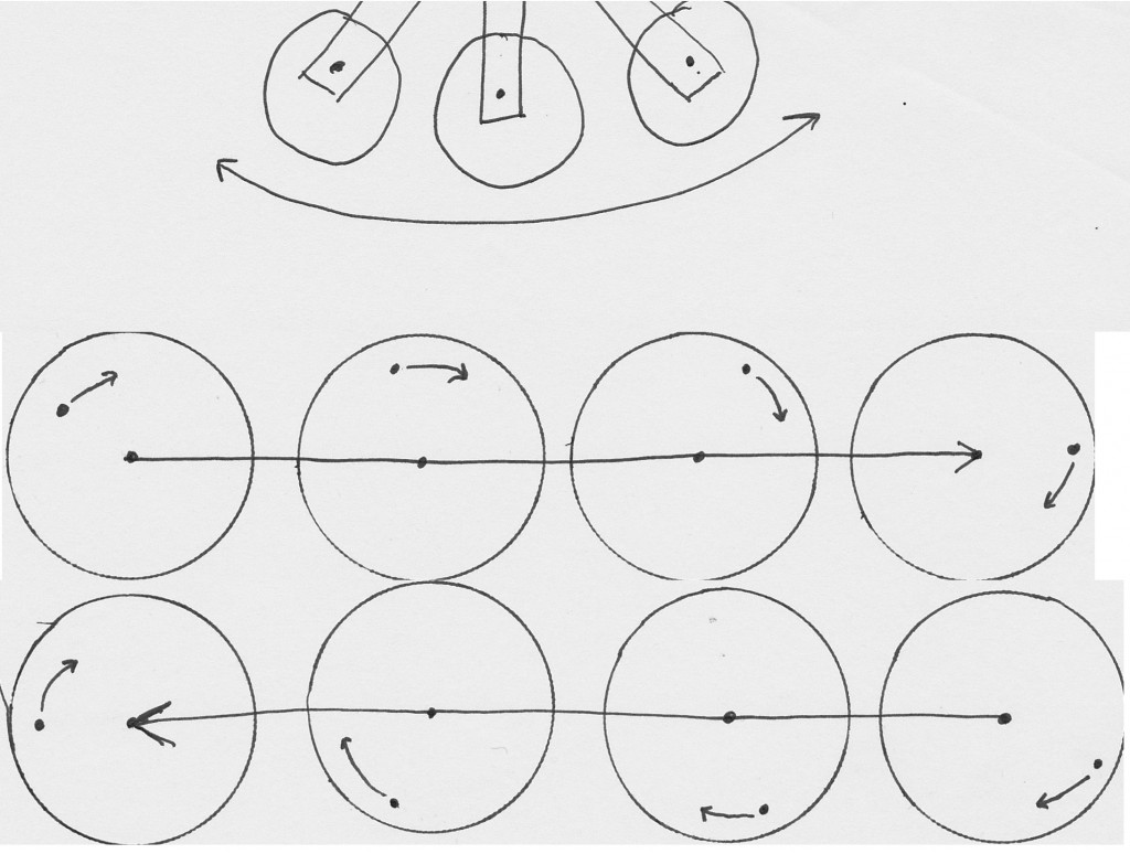
                          Ok - you see the top of the rods are attached to little bars or wheels at the end of the oscillating bars that rocks the lever back and forth. However, as the tops of the levers are rotating in a circle at the end of the oscillating bars - as the long crossbar goes back and forth, it changes the location in space where the center of axis is for the top of the lever moving in a circle meaning the motion IS elliptical.

                          It is only circular from it's own frame of reference between the top of the lever and its relationship to the center of axis around which the top of the lever is rotating. But what about the frame of reference between those little wheels or bars that spin the top of the lever in a circle and their position in volumetric space? It is moving back and forth while the top of the lever goes in a circle while that circle moves back and forth meaning the top of the input lever is moving in an ellipse.

                          Yes, the bottom of the lever follows the same pattern as the top, just scaled down but it is elliptical. Yes, top travels in a circle (while the whole circle is moving back and forth in space) - that equals an elliptical motion for the lever. If you zoom into the original video at that mechanism, at one point you see a white streak - moving from the right to left - from top view, it would be moving clockwise - that is the little wheel/bar moving in a circle at the end of the long crossbar.

                          That John Device isn't doing any real work other than overcoming bearing friction to move the weight at the bottom and that movement is directly proportional to the input motor. The claims of how much energy it takes to move the weight in a circle is misleading - apply a load to the bottom of that shaft and everything will come to a halt and the motor will smoke.

                          You should be able to copy and image from another location and paste it right into the post.
                          Sincerely,
                          Aaron Murakami

                          Books & Videos https://emediapress.com
                          Conference http://energyscienceconference.com
                          RPX & MWO http://vril.io

                          Comment


                          • lever elliptical orbit

                            This is how the top of the lever is moved in an elliptical orbit...

                            The crossbar that oscillates back and forth has a little wheel or bar at the ends and the lever is connected to that little bar or wheel. The little wheels go in a perfect circle, but over the journey of the movement of the long bar going back and forth, it traces an elliptical orbit. On the movement towards the right, you see it going on the top half of an ellipse and on the way back to the left, it traces the bottom half of the ellipse.

                            Sincerely,
                            Aaron Murakami

                            Books & Videos https://emediapress.com
                            Conference http://energyscienceconference.com
                            RPX & MWO http://vril.io

                            Comment


                            • Originally posted by Aaron View Post
                              Ok - you see the top of the rods are attached to little bars or wheels at the end of the oscillating bars that rocks the lever back and forth. However, as the tops of the levers are rotating in a circle at the end of the oscillating bars - as the long crossbar goes back and forth, it changes the location in space where the center of axis is for the top of the lever moving in a circle meaning the motion IS elliptical.

                              That John Device isn't doing any real work other than overcoming bearing friction to move the weight at the bottom and that movement is directly proportional to the input motor. The claims of how much energy it takes to move the weight in a circle is misleading - apply a load to the bottom of that shaft and everything will come to a halt and the motor will smoke.

                              You should be able to copy and image from another location and paste it right into the post.
                              Video clip of machine in first portion.
                              https://www.youtube.com/watch?v=xfAq7f-Y-A
                              As far as I know, this is the only evidence available for its function.

                              The top doesn't move except as the camera jitters a little to start (or rather the film is stretched and scratched to start with... so it's probably slightly twisted causing a side to side motion, which the whole machine undergoes.

                              Okay so I added a significant offset to the pivots of the joint... and ya, I guess it traces an ellipse. Although, with such a short end sticking out of the gimbal thing, not sure the eccentricity is even notable. I mean I have a 1.5 times longer shaft after the pivot than above... and a much more accentuated distance on the distance between the pivots....

                              offset uv joint.jpg
                              offset uv joint2.jpg

                              ahh the ATTACH tag

                              Re the guy that says manage attachments doesn't do anything maybe popups are blocked?

                              and regarding the john device... It's exactly the same thing, other than circular entirely and minus a load balancing top weight... the brunt of the work force is maintained. I could just cut an ellipse at the top and get the same result... though it'd require more force to get it around the 'corners'.

                              Comment


                              • And... it's a mutually cancelling eccentricity, if the top does move back and forth, and it's the lower pivot that determines the elongation, the lower pivot is an in-out direction, which would cancel the top side to side motion....
                                Edit:
                                actually it's probably the pivot mounted to the frame that determines eccentricity... so it may be accentuated... still see no motion in the top drive though.
                                Last edited by d3x0r; 07-06-2014, 09:05 PM.

                                Comment

                                Working...
                                X