Announcement

Collapse
No announcement yet.

William F. Skinner - 1939 Gravity Power

Collapse
X
 
  • Filter
  • Time
  • Show
Clear All
new posts

  • Originally posted by h2ocommuter View Post
    Try as I might I cannot get my bearings aligned correctly. As I believe this is the most important factor. I believe nearly all stress can be eliminated from this machine if this one factor is understood. I believe every care must be attended to in this exacting element of this invention by William Skinner.

    Here is a video of my failures today and some examples of what I see as the elemental behavior of failure to align correctly.

    Gravity 3 Bearing Alignment - YouTube
    Thank you for your continuing efforts and video.
    Looks like you have 5 power units around the central support.
    Just curious why you choose an odd number.
    Skinner's machine has 4 so the off center weights across from each other balance things out. will yours do that?
    I agree alignment is important.
    I think the input lever rod gimbal must be directly over the bearing under the universal joint at the bottom.
    What motion are the tops of the input lever rods making through the air?

    Keep up the good work.

    Tom

    Comment


    • (edit doesn't even work )
      Originally posted by Aaron View Post
      Just for fun, if you squeeze two opposing sides of your bucket together, you will make a somewhat elliptical shape for the roller blade wheel to move around.

      The John Device really is a completely different machine and has no ability to have any gain.
      Not possible to get kinetic energy from this?
      https://www.youtube.com/watch?v=gTWwp5qUY3U


      Circles are least effort (least required applied work)... ellipses will require more work to get out of the corners, because it will raise the mass more quickly in the corners... and a linear is the worst...


      At the ends, initially moving toward the center, the most force is used to change the tilt the most rapidly... (Red marks), and then slack off as it gets toward the center, and then on the falling side will accelearte to lead the drive, until it again has to be full force to lift the weight. The ellipse is the same thing, and depending on the eccentricity less and less. Until you get to a circle which (again) should be light blue and light pink dashes all along because it will inevitably accelerate past the drive always.... but the least force to get it to move is in a 1:1 ellipse. (unless starting for the side of an ellipse, then you just delay the issue... the total sum is 0 plus a little because of frictions. (of the drive force, not of the output force)

      I don't know why you're so set against the david machine with a single mass (again, you have to stop before adding more weights in balance which will reduce the effective kinetic power, even if gains potential power ... but that potential would be better stored in a flywheel.)

      I've tried 4 times to show the specific clip... but then I found that rohndoe has the clip of interest anyway https://www.youtube.com/watch?v=g3zs8vcBJyE indicating the pivots of the gimbal not set to provide an ellipse. If you're arguing that the deformation of drive rods causes ellipses; maybe... but 1:0.9 ratio is still a circle (10% deformation) and then it will be at arbitrary points with a precession...

      I'll be quiet here until I get my implementation more complete... if there truly is a gain, it should be able to accelerate itself. I paid to get an answer to the math, and have gotten nothing back. I saw your clip with graph paper and saying it's an ellipse, but you were driving it with a lever, which has subsequently been disproven (at least to me).

      I apologize for challenging your belief system. I have not said you are wrong.
      Last edited by d3x0r; 07-08-2014, 03:37 AM.

      Comment


      • 1939 Gravity Power Machine

        Originally posted by d3x0r View Post
        (edit doesn't even work )


        Not possible to get kinetic energy from this?
        https://www.youtube.com/watch?v=gTWwp5qUY3U


        Circles are least effort (least required applied work)... ellipses will require more work to get out of the corners, because it will raise the mass more quickly in the corners... and a linear is the worst...


        At the ends, initially moving toward the center, the most force is used to change the tilt the most rapidly... (Red marks), and then slack off as it gets toward the center, and then on the falling side will accelearte to lead the drive, until it again has to be full force to lift the weight. The ellipse is the same thing, and depending on the eccentricity less and less. Until you get to a circle which (again) should be light blue and light pink dashes all along because it will inevitably accelerate past the drive always.... but the least force to get it to move is in a 1:1 ellipse. (unless starting for the side of an ellipse, then you just delay the issue... the total sum is 0 plus a little because of frictions. (of the drive force, not of the output force)

        I don't know why you're so set against the david machine with a single mass (again, you have to stop before adding more weights in balance which will reduce the effective kinetic power, even if gains potential power ... but that potential would be better stored in a flywheel.)

        I've tried 4 times to show the specific clip... but then I found that rohndoe has the clip of interest anyway https://www.youtube.com/watch?v=g3zs8vcBJyE indicating the pivots of the gimbal not set to provide an ellipse. If you're arguing that the deformation of drive rods causes ellipses; maybe... but 1:0.9 ratio is still a circle (10% deformation) and then it will be at arbitrary points with a precession...

        I'll be quiet here until I get my implementation more complete... if there truly is a gain, it should be able to accelerate itself. I paid to get an answer to the math, and have gotten nothing back. I saw your clip with graph paper and saying it's an ellipse, but you were driving it with a lever, which has subsequently been disproven (at least to me).

        I apologize for challenging your belief system. I have not said you are wrong.
        I've tried every variation, circle, ellipse (mild ellipse) and linear. They do not do the same thing even though all three will make the bottom weight spin.

        With an ellipse, the "kinetic energy" is the greatest as it gets to the narrow end points and and requires the least amount of input to send it on its way to the other side.

        The circular method is like steady DC where you are constantly drawing a load, while the elliptical and linear are like higher efficiency pulsed motors that do not require constant input.

        You can say you can pulse the circular method, which is true, but you have absolutely no mechanical advantage at any point during the 360 degree rotation. With elliptical, you do as I mentioned above. You get a power increase, which is an impulse, and you don't get that with circular.

        Plus with a circular movement, you are not taking as much of an advantage of the mechanical reaction of the upper weight, which is intended to be "reacted" IN PHASE with the forward movement and with a circle, you deflect too much reaction out at an angle which is way more obtuse than you want. Unless you are considering these facts, you're looking at the machine in a compartmentalized way instead of taking it as a whole and are missing quite a bit of the picture. None of this is speculation.

        There is a way to mimic the mechanical advantage of an elliptical orbit using a perfectly circular rotation but I'm not going to go into it because it is related to a machine I developed that was inspired from the Skinner work in an attempt to simplify some of the concepts. It isn't as good as Skinner's but over 1.0 COP is over 1.0 COP.

        I'm not "set against" the David machine. It simply has no relation to the Skinner machine and everything from the input to output is in direct proportion to each other and gravity actually cannot contribute to anything the machine since the weights are in lockstep with the input motor. That means the whole point of using gravity as an energy source in that machine is completely defeated. The point of the Skinner machine is that everything is INDIRECTLY related meaning the output is not proportional to the input, but in the David machine it is. The Skinner machine is a non-equilibrium open dissipative system and the David machine is an equilibrium closed system that is shut off to environmental gravitational potential. These are facts.

        The gimbals are perfectly capable of allowing an elliptical motion. I don't understand how you can say they are not. Also, they're spring loaded or similar, which nobody seems interested in but it is completely common sense - look at that same video you linked to - the face of the gimbal on the right is not in lockstep with the lever there is an obvious lag at each end point that the lever reaches. This is why I said I have used rubber superballs as my pivot point before because the spring loaded gimbal" is a necessary buffer/dampener to ensure smoother operation of the machine.

        I have never argued anything about a deformation of the lever. Mike and myself have posted the mechanism at the top of the lever rod. The rods are rotated in an elliptical path - that is completely indisputable and it is easily observable in the very first part of the film.

        Go back and listen to my explanation on paper, I said it is mostly back and forth with some width to it meaning it is a narrow ellipse. That has never been disproved. Again, the mechanism is plain as day in the beginning of the film and Mike showed his interpretation of it and I showed mine - whether it is a little rod, wheel, etc... is irrelevant - the point is that at the end of the oscillating cross bar - the top of the lever goes in a circle while the center of the axis around which it rotates is moved through space meaning it is tracing an ellipse. That is completely indisputable and anyone that claims they have debunked this is completely out of touch with reality.

        I don't really have a "belief system". Some insincere people would have you belief I don't want to be challenged because they can't answer simple questions but if you pay attention to how it unfolded - it was he who started to challenge what I said about ellipses - but as soon as I challenge him to answer a simple question - look out!!! But what I am saying is not my speculation - it is all completely visible in the original video backed by experiments that I have done. Even without my own experiments, it isn't debatable what is in plain view right there in the original video.
        Sincerely,
        Aaron Murakami

        Books & Videos https://emediapress.com
        Conference http://energyscienceconference.com
        RPX & MWO http://vril.io

        Comment


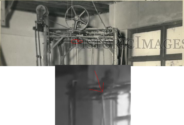
        • I found this picture

          @aaron
          Can you sketch on this picture where the moving part is that causes an ellipse?
          did a google image search for 'skinner 1939 miami' and found this for sale on Ebay...

          $_57.JPG

          Comment


          • Here are the images of the Skinner device from the ebay picture auction I enlarged and posted at the OU topic.

            Now, the question is, who here bought this picture? it was sold for $10. minutes before it was first mentioned at this topic.

            Also, look at the top mechanism, each side seems to have about 4 shafts to hold many gears in series to reach the final lever. So why would Mr. Skinner make it so complicated?


            Last edited by gotoluc; 07-08-2014, 01:10 PM.

            Comment


            • Originally posted by Aaron View Post
              I don't really have a "belief system". Some insincere people would have you belief I don't want to be challenged because they can't answer simple questions but if you pay attention to how it unfolded - it was he who started to challenge what I said about ellipses - but as soon as I challenge him to answer a simple question - look out!!! But what I am saying is not my speculation - it is all completely visible in the original video backed by experiments that I have done. Even without my own experiments, it isn't debatable what is in plain view right there in the original video.
              Good grief man.....let it go! We just disagree. Why do you keep bringing it up? I don't understand your creepy obsession with my comment.

              Comment


              • Thanks for posting those Luc.
                A couple days after the auction ended I emailed the seller to
                see if he could send me an electronic copy of the pic without the words "Historic Images" across it but I never heard back from him.

                Does anyone know how to contact the buyer?
                If so, maybe we could ask them for clear copy of it.

                Based on the picture, I drew out what I thought was a realistic representation of the drive gear/pulley train and counted 5 speed reductions from the electric motor to the input lever. I think that means the torque would be multiplied 5 times as well.

                The cotton thread must have been under fairly good tension and I think skinner must have had the motor on a quick release swivel plate so he could get the thread off/on without stretching/breaking it.

                What does using a cotton thread signify?
                Is it just proof that the whole drive train is very easy to turn or is it there to protect the motor similar to a fuse? or both?
                Anyone have any ideas about that?

                Tom

                Comment


                • Originally posted by gotoluc View Post
                  Here are the images of the Skinner device from the ebay picture auction I enlarged and posted at the OU topic.

                  Now, the question is, who here bought this picture? it was sold for $10. minutes before it was first mentioned at this topic.

                  Also, look at the top mechanism, each side seems to have about 4 shafts to hold many gears in series to reach the final lever. So why would Mr. Skinner make it so complicated?


                  Everyone seems to be missing a very important point. The top input shaft in the picture on the right side of the machine is clearly leaning out from the machine this shows that the top input shaft does rotate in a circle.
                  William Reed

                  Comment


                  • Originally posted by goldpro View Post
                    Thanks for posting those Luc.
                    A couple days after the auction ended I emailed the seller to
                    see if he could send me an electronic copy of the pic without the words "Historic Images" across it but I never heard back from him.

                    Does anyone know how to contact the buyer?
                    If so, maybe we could ask them for clear copy of it.

                    Based on the picture, I drew out what I thought was a realistic representation of the drive gear/pulley train and counted 5 speed reductions from the electric motor to the input lever. I think that means the torque would be multiplied 5 times as well.

                    The cotton thread must have been under fairly good tension and I think skinner must have had the motor on a quick release swivel plate so he could get the thread off/on without stretching/breaking it.

                    What does using a cotton thread signify?
                    Is it just proof that the whole drive train is very easy to turn or is it there to protect the motor similar to a fuse? or both?
                    Anyone have any ideas about that?

                    Tom
                    Hi Tom,

                    I would tend to believe that it's someone from this forum who has bought the picture. Look at the date and time the information was first posted and by the way, the link was for an auction that had expired (no bids) but it was re-listed as a buy it now (not an auction) and if you look at the date and time you'll be surprised.

                    I think the cotton tread demonstrates that mostly the rotation movement of the motor is used and not torque.

                    One thing I have mention and has been ignored is, why would Mr. Skinner go through the trouble of having the upper lever shafts turning when he could of just had a bearing in the mid (translation) plate? which would be quite similar to what Dave Q did, which he has demonstrated it can work.
                    What if Mr. Skinner was actually using the rotation force of the upper lever to assist (feedback) in the upper mechanism? As you can see there's a lot of pulleys up top

                    No one knows for sure how it works until you see them demonstrate a full working device (P in - P out) so anyone's guess is as good as the other.

                    Luc
                    Last edited by gotoluc; 07-08-2014, 05:30 PM.

                    Comment


                    • Originally posted by rosehillworks View Post
                      Everyone seems to be missing a very important point. The top input shaft in the picture on the right side of the machine is clearly leaning out from the machine this shows that the top input shaft does rotate in a circle.
                      Hi William,

                      I know it makes sense to think the levers are going in a circular motion when you consider the right and left levers are out. That's what I was thinking weeks back. But what if the right and left levers are going in and out and the front and back are going side to side?

                      Luc
                      Last edited by gotoluc; 07-08-2014, 05:34 PM.

                      Comment


                      • gotoluc,

                        I have been building machines for over fifty years. Many times I use parts already in my shop or parts off of the last prototype. This requires more thinking and more labor, but less money. I am building a full size replica of this machine. It will function as Skinner's does, but not have exactly the same parts. The gears on top may have been old threading gears off of lathes.
                        Garry

                        Comment


                        • elliptical mechanism

                          Originally posted by d3x0r View Post
                          @aaron
                          Can you sketch on this picture where the moving part is that causes an ellipse?
                          did a google image search for 'skinner 1939 miami' and found this for sale on Ebay...

                          [ATTACH]14612[/ATTACH]


                          X marks the spot. Top of lever on a little wheel at the end of the oscillator bar - its plain as day in the original film right in the beginning. You can see it rotating around as the oscillator bar goes back and forth. The water mark on that postcard is blocking it - it is easier to see in the original film - it is not hidden there.
                          Sincerely,
                          Aaron Murakami

                          Books & Videos https://emediapress.com
                          Conference http://energyscienceconference.com
                          RPX & MWO http://vril.io

                          Comment


                          • hypocrite

                            Originally posted by purelyprimitives View Post
                            Good grief man.....let it go! We just disagree. Why do you keep bringing it up? I don't understand your creepy obsession with my comment.
                            I'm tired of your mouth - your church comment was it. You're a complete hypocrite. You challenge my claims about the symmetry vs asymmetry but the moment I challenge you with a simple question that you don't have the guts to answer and then you attack me as someone who will only tolerate one viewpoint. Hypocrite.
                            Sincerely,
                            Aaron Murakami

                            Books & Videos https://emediapress.com
                            Conference http://energyscienceconference.com
                            RPX & MWO http://vril.io

                            Comment


                            • elliptical orbit

                              Originally posted by gotoluc View Post
                              Hi William,

                              I know it makes sense to think the levers are going in a circular motion when you consider the right and left levers are out. That's what I was thinking weeks back. But what if the right and left levers are going in and out and the front and back are going side to side?

                              Luc
                              The levers are going in a circle on the end of the oscillator bar while the oscillator bar goes back and forth - what does that tell you? It is tracing an elliptical path. It is not a guess that is as good as anyone's, it is a fact that is right there in front of everyone's face in the beginning of the video.
                              Sincerely,
                              Aaron Murakami

                              Books & Videos https://emediapress.com
                              Conference http://energyscienceconference.com
                              RPX & MWO http://vril.io

                              Comment


                              • Originally posted by gotoluc View Post
                                Hi William,

                                I know it makes sense to think the levers are going in a circular motion when you consider the right and left levers are out. That's what I was thinking weeks back. But what if the right and left levers are going in and out and the front and back are going side to side?
                                Luc
                                When looking at the video it is clear that all the top bars move the same in and out, and back and forth.

                                I am NOT here to stir up any conflict so I will stop talking about it now. Thanks for your reply.
                                William Reed

                                Comment

                                Working...
                                X