Announcement

Collapse
No announcement yet.

William F. Skinner - 1939 Gravity Power

Collapse
X
 
  • Filter
  • Time
  • Show
Clear All
new posts

  • synchronous design?

    Originally posted by goldpro View Post
    Thank you for your continuing efforts and video.
    Looks like you have 5 power units around the central support.
    Just curious why you choose an odd number.
    Skinner's machine has 4 so the off center weights across from each other balance things out. will yours do that?
    I agree alignment is important.
    I think the input lever rod gimbal must be directly over the bearing under the universal joint at the bottom.
    What motion are the tops of the input lever rods making through the air?

    Keep up the good work.

    Tom
    Thanks Tom, We will never know until we try. The dispersion of energy via counterbalance is not an element I am concerned with at this stage. I chose 5 because it was easy for me to understand how to build. 6-8-or 12 would have been fine choices as well but I wanted to keep it modest and learn as much as possible about the dynamics of a fine tuned and productive model. That is really the only reason. NOT Another reason is I had convenient drive motors that can be powered with little energy and a belt drive that requires a near friction-less machine to drive. If I am correct my motor will lift 4.5 lbs "5 Pepsi cans" My wife( lives on pepsi)and spin them. I do not know how much energy that will be but it is a simple math equation to figure it out. Thirdly The drive shafts and u-joints were cheep, and bearings too. Well there were other reasons that I chose this size but to answer the question about balance. I believe the geometric pattern I chose has a 25 percent better balance than Skinner's. I may be wrong; but it won't. My shop is really poor.

    My point is two fold.... Skinner took 14 years and built at least 4 various models. There is no way I could possibly understand everything he had learned by watching the video and summarily building one of my own units out of balsa wood and particle board.

    I really have an advantage of starting my build with this small scale and lite wood parts. Really I can readily see where the weaknesses are and look to the outcome to see the strengths, or the structural strength needed for each component. There is really a lot of heavy duty math timing and engineering in this machine of Skinner's and that is what makes it fun for me.
    Really This is a learning experience and I am having fun doing it and sharing.

    I am next to the stage of reinforcing the rotary drive fulcrums. the motor driver is rotating in an adjustable circle that can rotate as far as 3.5" all the way down to (0). without any stabilization. I can get rotation at about 1" circular motion. The deflection reduces the actual action to about 1/3 to 5/8 "of that 1". with stabilization I should be able to get 80 to 95% with pepsi. This driver is Monosynchronous, My meaning is all units will turn to the same clock position at all times. My reasoning is this: My unit will only be driven to an RPM that will inhibit all spurious energy ie; excessive centrifugal energy. I do believe this can be useful but at this stage I will be more concerned with understanding the counterbalance weight and what it's purpose is!

    Thanks for the comment Tom
    Comment


    • Originally posted by Aaron View Post


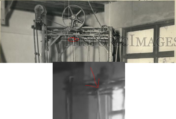
      X marks the spot. Top of lever on a little wheel at the end of the oscillator bar - its plain as day in the original film right in the beginning. You can see it rotating around as the oscillator bar goes back and forth. The water mark on that postcard is blocking it - it is easier to see in the original film - it is not hidden there.
      Nothing is clear as day in the first 3.5 seconds of video
      https://www.youtube.com/watch?v=xfAq7f-Y-Ao (first 28 seconds are youtube scaling processing to 1/8 speed last 3.5 seconds is original speed)

      The light spot just sits there, it's part of the background. it's a view between the gear so you can see the light back wall. and an artifact of video encoding. The light spot sits in place and doesn't move with the shaft.

      Another example the left bar starts to go past the front support, but then the film jumps, and the averaging picks it up as the the tranition as a motion into the back vertical drive shaft...

      Comment


      • Originally posted by purelyprimitives View Post
        One interesting thing I just now noticed in the photograph. It 'appears' that all 4 arms are pointing out.

        I realize that the machine is at rest here but I thought the 4 arms were tied together mechanically at the top and adjacent arms were always 90 degrees out of phase so that when one opposite set is furthest apart (pointing outward), the other set are closest together (pointing inward). But in the photograph, they are all pointing out??

        Can anyone reconcile this?
        They are 90 degrees out of phase no each arm... when 2 opposing are inside, the outside opposing are inside. This provides a balance to the whole machine so it doesn't walk across the floor like an off-balance washing machine...

        https://www.youtube.com/watch?v=4vCs4atKqBU

        Comment


        • Originally posted by gotoluc View Post
          Have a look at this looped video I made back in May and posted at the OU forum topic.

          Look only at the left side upper lever. You'll see the lever travels away from the side steel frame but when it comes back in it doesn't travel inwards as much as it travels outwards. You can't even see the very top of the lever pass the other side of the steel frame.

          Link to video: http://www.overunity.com/14655/1939-...attach/138942/

          I think this would support the half circle motion, would it not? ... or at least an elliptical that is offset to the outside of the frame.

          Luc
          Not really; only supports that the angle of the shot puts the front foreground thing to cover more than half the rotation.

          Comment


          • Originally posted by d3x0r View Post
            They are 90 degrees out of phase no each arm... when 2 opposing are inside, the outside opposing are inside. This provides a balance to the whole machine so it doesn't walk across the floor like an off-balance washing machine...

            https://www.youtube.com/watch?v=4vCs4atKqBU
            I agree. I was just trying to reconcile the foreground and background upper lever arms in the picture which both seem to be tilted out, when they should be tilted in.

            Great washing machine vid by the way....

            Comment


            • Turning levers etc...

              Originally posted by gotoluc View Post
              Here are the images of the Skinner device from the ebay picture auction I enlarged and posted at the OU topic.

              Now, the question is, who here bought this picture? it was sold for $10. minutes before it was first mentioned at this topic.

              Also, look at the top mechanism, each side seems to have about 4 shafts to hold many gears in series to reach the final lever. So why would Mr. Skinner make it so complicated?


              For everyone contemplating the elliptical orbit probability I would cite a couple of elements that may be of interest.

              I clearly see the upper levers rotation and that tells me to look below.. inside the spring bearing /gumball (way too big) I see a "cam lobe", that would rock the boat and take the wobble out of the elliptical orbit! The upper attachment to the levers is the holding bar that holds the lever causing the rotation on the lever into the gumball/spring thingy, cam lobe. the upper bar that holds on to the lever and attached to the pulley seems to have that elliptical orbit. (I see all of this) Quite complicated to say the least. but makes sense to me. it would take a lot of tooling so I chose an easy way for me.

              The thread being small is qualified to me in a couple of ways. first off what an elegant question! "The gear reduction math" I believe someone already has done that, which equals very low energy to turn the machine. The possibility that this could be a fuse type fail-safe to alleviate gear breakage is reasonable but the probable reason in my mind is that the machine turns very freely. nearly without effort.

              Has anyone taken the measurements to find out what angle the weights are hanging on? I mean The angle of the weighted fulcrum from the offset shaft to the pivot bearing on the ground from vertical.? I just guess at 4' / 2" .041 degrees offset. that .04 percent is serious amount of energy potential.

              A 4 percent grade in a big truck will push lots of free energy! down the hill...

              Oh another question about the P in to p out.
              1/5 hp in times 1200
              .2 which is 1/5 of a whole say 1 hp * 1200 equal 240 hp
              Skinner was surely not using 240 hp in his shop the way it looked.

              Comment


              • elliptical path for the top of the lever

                Originally posted by d3x0r View Post
                Nothing is clear as day in the first 3.5 seconds of video
                https://www.youtube.com/watch?v=xfAq7f-Y-Ao (first 28 seconds are youtube scaling processing to 1/8 speed last 3.5 seconds is original speed)

                The light spot just sits there, it's part of the background. it's a view between the gear so you can see the light back wall. and an artifact of video encoding. The light spot sits in place and doesn't move with the shaft.

                Another example the left bar starts to go past the front support, but then the film jumps, and the averaging picks it up as the the tranition as a motion into the back vertical drive shaft...
                Look at it looped makes it very obvious that lever rotates in a circle while the circle's axis is moving back and forth on the crossbar - that makes an elliptical path that is shaped a bit like a smile.

                The only reason the top of any of the levers go past the perimeter of the main frame of the machine is because the little wheel/cam that the lever is connected to is whipped out away from the oscillating crossbar. In the beginning of the film it happens when the lever is moving towards our left, then when it goes right, the wheel/cam whips the lever around towards the inside of the cross bar. It is the upper weight on the translation coupler that helps to reinforce this movement as the lever only needs to make up for the loss.

                The travel of the left and right of the crossbar is quite a bit more than the travel of the forwards and back of the wheel/cam meaning it is an ellipse.
                Sincerely,
                Aaron Murakami

                Books & Videos https://emediapress.com
                Conference http://energyscienceconference.com
                RPX & MWO http://vril.io

                Comment


                • Originally posted by h2ocommuter View Post
                  Oh another question about the P in to p out.
                  1/5 hp in times 1200
                  .2 which is 1/5 of a whole say 1 hp * 1200 equal 240 hp
                  Skinner was surely not using 240 hp in his shop the way it looked.
                  it's cited as 1200%
                  100% = * 1
                  so 1200% is only *12.
                  and it's 1/8 horsepower... so it's 2.5HP out.

                  100 per hundred (per cent) = 1 per 1...

                  Comment


                  • Originally posted by Aaron View Post
                    Look at it looped makes it very obvious that lever rotates in a circle while the circle's axis is moving back and forth on the crossbar - that makes an elliptical path that is shaped a bit like a smile.

                    The only reason the top of any of the levers go past the perimeter of the main frame of the machine is because the little wheel/cam that the lever is connected to is whipped out away from the oscillating crossbar. In the beginning of the film it happens when the lever is moving towards our left, then when it goes right, the wheel/cam whips the lever around towards the inside of the cross bar. It is the upper weight on the translation coupler that helps to reinforce this movement as the lever only needs to make up for the loss.

                    The travel of the left and right of the crossbar is quite a bit more than the travel of the forwards and back of the wheel/cam meaning it is an ellipse.
                    Here's it looped I dunno 7 or 8 times... tried to patch together so the end of one starts back in the beginning, as judged by the right side weight being out. There's still a lot of jitter.... The light spots are still not moving... still think it's artifacts from encoding; would be nice to get a super high res conversion, since the source is only 360, it's only like 8 pixels that contain the operation in question... and the's being generous it's probably more like 3.5x1.2 pixels, so the averaging of the background and the light lever make a bar..(I do see a bar-like thing... )

                    https://www.youtube.com/watch?v=4EpFlBsbXkE

                    The top drive gear extending beyond the machine is clearly seen in the previously posted press photos... so the only reason it goes beyond the frame is... cause it's mounted on a circular gear that goes beyond the frame.

                    Whipping, with such a large mass is not going to be conducive to this situation, it's just a requirement for more input.
                    ----
                    My setup almost works; need to reinfoce my axle - it bends enough degrees with a few pounds so the bottom isn't actually tipped...
                    rodbend.png
                    ---------
                    This picture is 'a solar flare, or the face of evil?'

                    This one looks more like a face...
                    http://www.energeticforum.com/attach...1&d=1404906768
                    solar-flare2.jpg
                    Just sayin....
                    Last edited by d3x0r; 07-09-2014, 11:57 AM.

                    Comment


                    • Here's another looped view where the rotation of adjacent levers can be clearly seen rotating in a circle. If there is any elliptical motion here it must be very tiny because they both appear to have the same rotation angle:


                      https://dl.dropboxusercontent.com/u/...%20turning.wmv

                      Comment


                      • lever rotates in an elliptical orbit

                        Originally posted by d3x0r View Post
                        Here's it looped I dunno 7 or 8 times... tried to patch together so the end of one starts back in the beginning, as judged by the right side weight being out. There's still a lot of jitter.... The light spots are still not moving... still think it's artifacts from encoding; would be nice to get a super high res conversion, since the source is only 360, it's only like 8 pixels that contain the operation in question... and the's being generous it's probably more like 3.5x1.2 pixels, so the averaging of the background and the light lever make a bar..(I do see a bar-like thing... )

                        https://www.youtube.com/watch?v=4EpFlBsbXkE

                        The top drive gear extending beyond the machine is clearly seen in the previously posted press photos... so the only reason it goes beyond the frame is... cause it's mounted on a circular gear that goes beyond the frame.

                        Whipping, with such a large mass is not going to be conducive to this situation, it's just a requirement for more input.
                        It it not an artifact of the film, the opposite side is doing the same thing.

                        Whipping the lever out away from the crossbar is not whipping a large mass...it is simply moving the lever on a pivot. Your claim is contrary to the very point of the machine.

                        If you understand how a lever and fulcrum works, the whole point is to not have to manage a large mass with a lot of force over a small distance, it is to manage a large mass with flea power over a larger distance. And once the machine is up to speed, the upper weight does 99.99% of the work in rotating that translation coupler and changing the center of gravity of the lower weight - the lever only has to make up for the loss.

                        That is a universal principle that applies to virtually every non-equilibrium machine whether it is mechanical or electrical. Any claim that is in opposition to these universal principles is false at face value.

                        It is not a requirement for more input, it is the opposite - it reduces the input. It is a positive feedback system and this is because the reaction in the machine helps to move it forward. If it did not do that, the lever would have to work against resistance and it does not. The upper weight is doing most of that work as described above.
                        Sincerely,
                        Aaron Murakami

                        Books & Videos https://emediapress.com
                        Conference http://energyscienceconference.com
                        RPX & MWO http://vril.io

                        Comment


                        • lever moves elliptically

                          Originally posted by purelyprimitives View Post
                          Here's another looped view where the rotation of adjacent levers can be clearly seen rotating in a circle. If there is any elliptical motion here it must be very tiny because they both appear to have the same rotation angle:


                          https://dl.dropboxusercontent.com/u/...%20turning.wmv
                          You're looking at the elephant's leg trying to explain the elephant. Judging what it is doing by looking at the bottom of the lever near the pivot serves no purpose.

                          There is nothing rational about drawing any conclusion from that clip as there is not enough information.

                          You have to account for the actual mechanism at the top as the lever oscillation is much wider than the throw of the cam/wheel. It is not a mild ellipse at all.
                          Sincerely,
                          Aaron Murakami

                          Books & Videos https://emediapress.com
                          Conference http://energyscienceconference.com
                          RPX & MWO http://vril.io

                          Comment


                          • I stabilized the top part to help see better

                            skinnertop2
                            and
                            skinnertop3
                            and
                            full looped skinnertop4
                            Last edited by drak; 07-10-2014, 01:15 AM.

                            Comment


                            • Originally posted by Aaron View Post
                              You're looking at the elephant's leg trying to explain the elephant. Judging what it is doing by looking at the bottom of the lever near the pivot serves no purpose.

                              There is nothing rational about drawing any conclusion from that clip as there is not enough information.

                              You have to account for the actual mechanism at the top as the lever oscillation is much wider than the throw of the cam/wheel. It is not a mild ellipse at all.
                              If I had absolutely no idea what an elephant looked like, you would be correct. However, I have seen an elephant many times and if I could only see a leg, I wouldn't need to see anything else to know it was an elephant.

                              That being said, regarding the overall top mechanism, we don't really have much to go on with the exception of some very grainy film and some educated guesses.

                              Comment


                              • elliptical path

                                Originally posted by drak View Post
                                I stabilized the top part to help see better

                                http://vimeo.com/user25636515/review/100346315/fb12d310aa
                                and
                                skinnertop3
                                and
                                full looped skinnertop4
                                Good job on that! The red filtered version makes it even easier to see that the rod closest to the camera is obviously doing exactly what I explained.
                                Sincerely,
                                Aaron Murakami

                                Books & Videos https://emediapress.com
                                Conference http://energyscienceconference.com
                                RPX & MWO http://vril.io

                                Comment

                                Working...
                                X