Announcement

Collapse
No announcement yet.

William F. Skinner - 1939 Gravity Power

Collapse
X
 
  • Filter
  • Time
  • Show
Clear All
new posts

  • misinformation propaganda

    Originally posted by purelyprimitives View Post
    If I had absolutely no idea what an elephant looked like, you would be correct. However, I have seen an elephant many times and if I could only see a leg, I wouldn't need to see anything else to know it was an elephant.

    That being said, regarding the overall top mechanism, we don't really have much to go on with the exception of some very grainy film and some educated guesses.
    Your logic is bastardized - you and a handful of others have said the video isn't clear enough to tell what is going on - therefore, you still have no idea what the elephant looks like. Your above bolded quote proves my point. Yet, with your analogy you claim to know what the elephant looks like.

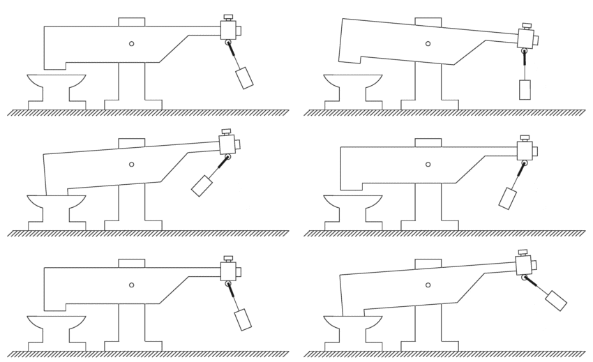
    It is clear to me and a few others and that red filtered video clearly shows 100% exactly what I described. The height of the rod shortens as it gets to the end of the left side and starts to go right because it is tipped away from the camera meaning it would appear slightly shorter on its way back to the right - 100% exactly as depicted in the diagram I posted.

    Also, your circular claims falls flat and is inconsistent with how the translation plate operates - you are doing nothing more than pushing your theories while I actually have had the mechanism worked out in an actual model for over 1.5 years. You can talk all you want but until you build something, you don't know what does what. I'm speaking from experience while you are not. I am not operating on educated guesses, while you think you are - I am giving explanations based on successful demonstrates of the mechanism and I know what method gives the highest advantage as I have measured them all.

    Everything I have explained accounts for the gains in the machine, while your claims actually negate the entire point of the machine. So, what is your point? You can't get the gains with a circular mechanism and if that is what you believe it is, you're wasting your time and everyone else's because it contradicts the claims of the machine.
    Last edited by Aaron; 07-10-2014, 12:17 AM.
    Sincerely,
    Aaron Murakami

    Books & Videos https://emediapress.com
    Conference http://energyscienceconference.com
    RPX & MWO http://vril.io

    Comment


    • For some reason the first video was giving permission denied, fixed and edited previous post.

      Comment


      • Skinner Gravity Power Machine operation methods

        It should be common sense that the oscillating crossbar mechanism with a wheel/cam at the end would not be necessary if the point was to rotate the lever in a circular motion. There are countless simple ways to do that without this kind of setup and Skinner was obviously brilliant enough to know this as evidenced by his engineering marvel. Any claim about building a Rube Goldberg machine in order to rotate something in a circle is completely laughable.


        Skinner's machine is elegant and takes a very short path from A to Z.

        Anyone pushing the circular argument, pun intended, does not understand the dynamics of the ellipse, does not understand what power amplification is, and does not understand anything about gravity.

        Gravity is a push - not a pull and is the effect of aetheric gravitational potential being displaced by the mass of the Earth. As it rebounds back to where it was displaced in dynamic fashion, the positive potential of the aether imparts an electrostatic push against the protons that make up the mass exerting a repulsion against it holding it to the ground.

        As the lower weight is spun around, gravitational potential is rebounding vertically towards the ground but when encountering mass moving perpendicular to the direction of the gravitational potential's propagation, some of the gravitational potential energy will push the weight down and some is deflected perpendicular on the mass to push it out (centrifugal force).

        The faster a mass spins, the more gravitational potential is deflected 90 degrees to its original direction of propagation giving more of an outward push compared to down and the weight will actually raise upwards since less gravitational potential is pushing it down. That is not a conversion of gravitational potential to centrifugal force, it is gravitational potential energy simply having its direction changed by the perpendicular deflection of a rotating mass.

        This is the primary source of the source potential that turns into work when encountering resistance when interacting with the mass of a rotating object (lower weight). So when this machine is described as being a gravity power machine, that is exactly what it is and anyone making claims to the contrary is blowing hot air.

        When the machine is up to speed and everything is synchronized, the upper weight's momentum carries the translation coupler around and does most of the work to change the center of gravity of the lower weight/shaft in order to move it and get it to constantly fall in an elliptical rotation.

        The only function of the input lever at this point is to simply make up the loss on each rotation of the upper weight to shift the center of gravity of the lower weight.

        These are universal principles. Anyone that has built electrical circuits that recover a high percentage of the input knows that you only have to supply just enough to make up for the loss in order to get the full work out of the circuit.

        In a mechanical machine, the Veljko 2 stage oscillator is the same thing - the only input necessary to input into the pendulum is just what is needed to make up for the loss and that is it while the machine happily oscillates about producing many times the mechanical work compared to the input.

        The Skinner machine is the same way as it is not immune to following the principles that govern non-equilibrium systems and this particular principle is what the input lever does when the machine is up to speed.

        The Skinner machine's input uses the advantage of the elliptical path because at the end points - the far right and left of the lever action, the kinetic energy is the highest of the upper weight and when injecting fly power to make up for the loss, it is working in phase with the operation and there is a power amplification at these points that are 180 degrees from each other.

        Only those who are skilled in the art will understand this and anyone claiming the mechanism is circular is absolutely not able to comprehend how the machine even works or where the gain mechanisms are.

        Even if you are not "skilled in the art" and want to understand the machine, the facts have already been explained and if you build it according to what is described, you will be replicating the Skinner machine. Wasting time with circular input, etc. will only lead to disappointing results, which appear to be what is desired by a hand full of people, in order to discourage people from learning the truth about this machine.

        Claiming the Skinner machine rotates the input lever in a circular manner is like claiming the Bedini SG draws constant current from the input battery, which is completely ridiculous, but that is an accurate exact analogy.

        The ellipse serves a purpose of creating a condition where the speed is able to be amplified by having an ebb and flow intrinsic in the ellipse that gives a speed increase with the weight in order to give a mechanical advantage that gives an ideal point of where to inject more input energy from the lever.

        There is both power amplification and energy amplification in the Skinner machine and those pushing the circular argument are unaware of the different and unaware of how they both apply to the Skinner machine.

        I don't appreciate prospective builders and new members being abused by those that are really making claims without knowing what they're talking about.

        First, power amplification has to be understood and when that is comprehended, then amplified power over time needs to be understood, which is an energy gain.

        The Skinner machine makes use of gravitational potential energy and turns it into actual dissipative mechanical work so no longer potential energy but real energy dissipated over time.

        Flea power from the input lever to make up for the loss in the rotation of the upper weight swinging the translation coupler around, which changes the center of gravity of the lower weight to cause it to constantly fall to the incline of the lower shaft produces mechanical work in excess of what is needed to make up for the loss on each rotation by the input lever.
        Last edited by Aaron; 07-10-2014, 01:35 AM.
        Sincerely,
        Aaron Murakami

        Books & Videos https://emediapress.com
        Conference http://energyscienceconference.com
        RPX & MWO http://vril.io

        Comment


        • input lever mechanism

          Originally posted by drak View Post
          For some reason the first video was giving permission denied, fixed and edited previous post.
          Thank you - works for me now.
          Sincerely,
          Aaron Murakami

          Books & Videos https://emediapress.com
          Conference http://energyscienceconference.com
          RPX & MWO http://vril.io

          Comment


          • I like brainstorming

            I looked at the leg of the top-rod.
            at t=35 seconds William grabs an iron part with his left hand, and the camera takes a nice front view of the machine.
            I am zooming in on the left side of the machine (the side parallel to his left hand). The rod goes through the gimbal and you can clearly see the lower (piece of) the rod. Now remember, the machine has 4 quadrants, all with the same build. meaning: if you see a left quadrant piece and a 90 degrees next quadrant of that same piece, you have a view from both sides.
            So now I review the same video part (I do a step by step view on my PC on a local file of course).
            The camera pans down, and William walks away.
            At that point you can watch that same piece from the right side.
            If you go step by step, and count the frames and measure the distance it travels, you will see a sinusoidal movement, meaning it is elliptical.

            I have read all the threads here, but I stick to what I see. And I use all opinions here to try and convince me otherwise as I try to be open to new input.

            What I think I see:
            1) the top consists of 4 round wheels, rotating in a circular fashion
            2) the top-rod goes through a gimbal and below that gimbal is an opening in the steel (that opening is round as well, otherwise the rod would bump)
            3) the top rod now enters a piece of steel, it looks like many drawings already shared here, and we have all seen it very clear. I do want to add that yuo can see this piece of steel tilting! The tilt shows that it is not mounted-fixed, and taht the top-rod attached to it is leaning forward constantly
            4) The smaller weight is being turned round and round and actually driving the lower weight (in a loosely coupled or indirect fashion)
            5) the bottom is circular as well

            It is a device with 2 stages, the top stage has a weight which is tilted slightly so it keeps falling, this is stage one. The wight as well has inertia and stabilizes the movement for the weight below it. The second stage has one freedom more than the top movement, its axis can rotate more freely.

            I have done some simple tests with a bucket and such (you have seen it). The hint of squeezing the bucket had a negative result, as the movement of the rod now is strongly opposed on the long sides! The mass does not want to start moving as there is an incredible amount of power needed to get it going. And if you start is manually, the non-circular movement is making the movement unstable.

            I understand the idea behind an elliptical trajectory, as it makes us compare the movement with pushing a swing. But how does that idea fit in this device?

            Aron, please do not respond to my opinions, you could say 'every view on this system is a view (opinion, impression) and people should read all opinions and may trust on their own intuition or science to determine their opinion.

            I have some thoughts I need to share, I just forget to write them down .. ..
            * if this device works (and I am sure it does, same for the John Device) then F=m*a applies. meaning: we can remove 'gravity' and use a strong spring which has a very constant tension as it is stretched over a certain length.
            * and: even more: if it works with gravity or a spring, it will work with magnets as well. (in theory)

            * I saw people writing about the calculations, 1200%. But if you read that news paper article then it describes William talking about an 'if' statement.
            Line 1, I quote: "he believed the machine's principle could be carried to a point where a one-horsepower motor would provide electricity for a community of 3500 people at a total costs of only $5 a month"
            Line 2, I quote: "Skinner estimates the "gravity power machine" would increase the horsepower motor about 1200 percent"
            Line 3, I quote: a one horsepower, he believed, with a perfected "gravity power machine" to multiply its output, could be made to drive a generator large enough to produce electricity for 3500 persons (not households).
            Being a programmer I clearly see an if statement
            IF we had a one horsepower motor
            AND we had a perfected "gravity power machine"
            THEN we could have that output for 3500 people

            What is not said here, is that Skinner adds up details
            * a 1 HP motor can be increased to 1200% (12 times) its output
            * a perfected "gravity power machine" must be created. His own device has 4 units, the perfect unit would have .. .. fill in the blanks .. .. perhaps 50 units

            We should read between the lines.
            Also: on a description on the internet was said Skinner drove his workplace for $5 a month. So 1 1/8 HP motor driving costs $5, and Skinner states a 1 HP motor driving costs $5 as well. I think the more often someones story is cited, the more it changes.

            As I am not an engineer, I am hoping any input we share with each other helps each other to get to a replica.

            O, not to forget, something I saw as well.
            The editor left out a small part of the video (the mounting a rope and actually really starting the device).
            We see Skinner push the button of the motor with his right hand, shutting it down. Then he removes the cotton wire. When the wire is removed he pulls a weight. Notice: the drive wheel (top left in the movie) is rotating. And the wheel increases speed as the weight gets closer. So this is the feedback via that small steel plate from the top weight to the top rod (shaft) and that wheel on top. Also check and see that the weight to his right now also starts to move (also the other one in the far end, but that is harder to see).
            Next clip: the camera now shows a new setting, shot from the legs upwards, William pushes a weight once. Next clip: Hey: there is a ribbon on the motor now! So that last clip was made (minutes) later as the device is now running low speed (I counted 8 rotations and timed 8 seconds which is 60 RPM)

            I would appreciate if we (here on the forum) would not try to convince people a writer here is wrong. No. I would appreciate if we all just share our thoughts. So if we would not use words like 'xx is wrong'. There is not working or right, there is no one here that actually has seen the device. We don't have Nikola with us who can see a device like this working in his head. We need to TRY replicating in as many ways we can. Does it bother if we make a device not working? No. I uploaded my silly demo just to show anybody can do some tests. And the best part of it: dong that test convinces me this device is for real. So who reads this: if you need motivation, just build a simple version, all you need to feel is the additional power you get from tilting the shaft.

            One more thing I am thinking of. If you spin up a bicycle wheel, and try to change the position of the axis (wheel vertical, axis horizontal, try and move the axis up and down), you will notice it takes a lot of effort to get this done. But if you have the axis in two hands, and you now start making circles with your hands, the wheel looks to slow done in rotation and there is almost no inhibition anymore. (second part is off-topic). So a rotating mass will try to keep moving the same (horizontal, rotating) path. In addition: spinning that wheel, if I hold the left hand still and rotate with the right hand I feel a counter force. So keeping one side fixed does this. If both hands rotate (like pedaling a bicycle, one hand goes up, other goes down) then the wheel follows with almost no counter force. I see a direct relation of this knowledge to the Skinner device.

            Sorry I am posting all in one. I like brainstorming, and I hope there are people who think the same.

            Comment


            • Originally posted by Aaron View Post
              Also, your circular claims falls flat and is inconsistent with how the translation plate operates - you are doing nothing more than pushing your theories while I actually have had the mechanism worked out in an actual model for over 1.5 years. You can talk all you want but until you build something, you don't know what does what. I'm speaking from experience while you are not. I am not operating on educated guesses, while you think you are - I am giving explanations based on successful demonstrates of the mechanism and I know what method gives the highest advantage as I have measured them all.
              Gee Aaron why didn't you just say this before? Just point me to where you've published this data and we can put the issue to rest. Hopefully you have a video showing the actual test measurements.
              Last edited by purelyprimitives; 07-10-2014, 12:07 PM.

              Comment


              • Aaron, I think we would all be very interested in your test data. I thought from your videos you only had some test mock ups of a few of the sub systems. You hold the keys to a remarkable machine brought back to life. You could save millions from thirst and poverty.
                Thanks
                Garry

                Comment


                • aaron thats why you have been so angry with circle talk.

                  could you help me in some details,
                  is top rod fixed to gimbal or is it fixed to plate of the 1 weight.
                  fixed from falling not from turning .

                  Comment


                  • Originally posted by turbogt16v View Post
                    aaron thats why you have been so angry with circle talk.

                    could you help me in some details,
                    is top rod fixed to gimbal or is it fixed to plate of the 1 weight.
                    fixed from falling not from turning .
                    I'm here in France and it is raining cats and dogs, 12c and lit the fire at my father inlaws to keep warm, not used to this weather

                    My take is it is fixed to the plate, that is why the rod turns, it passes through the gimbal being able to rotate. It is this rotation that interreacts with the cam on that wheel, which in turn creates the movement of the lever.

                    regards from a wet France and tour de France

                    Mike

                    Comment


                    • Once upon a time, motors were rare, and man-power was more common. So there's this thing called a 'treadle lathe' which is a foot powered machine with a flywheel. All of the flywheels mentioned in association with metal-turning are pretty tiny, in comparison to the mass used in this. Using a tilted axis to accelerate the masses is going to be less effort than foot power to accelerate, but it's all a matter of leverage, since the lever is like 24 times longer on the top, plus only a few degrees of angle to get the mass moving... the skinner machine has a HUGE amount of mass, way in excess of what used to be used for Antique treadle lathes (images)

                      This site Portass Lathes has a HUGE list of lath manufacturers... I did not dig through to see if I could find anything even slightly more comparable. (link is on specifically portass that has a dreadnaught lathe... and images larger flywheels that can be used to attach to various models)

                      Antique Cast Iron Treadle Lathe
                      ay63.jpg

                      Portass Lathes
                      img20.jpg

                      ----
                      With one weight in john device style, I can say there is no gain. If you take the power immediately in a self-feedback system, there is a gain of 0 and the machine sits there. Adding more weight makes it move slightly, but that's only the amount of acceleration from stopping the falling mass as you put it on. I don't have a good way to make a video of this since it's such a large thing. I have a very small divot in the wheel I used at the top of the lever (less than 1/64th of an inch) and I looked and looked and didn't see it until I had the machine in a certain position that had a skip in the motion of the top of the axle... noting that position I finally saw the flaw. My shaft is about a 3.5 degree tilt....

                      The length of the axle below the mass arm determines the maximum height difference the mass can have... and a shorter arm is less work to raise the weight. So not only is the top shaft like 24:1 the lower tilt axis is another 24:1 which gives 576:1 effective leverage on the weight.

                      The separate rotating mass at the top that adjusts for tilt will help the motion be overall more fluid when for example the lathe bit is first applied to the rod... but as in many 'overunity' videos there is only a short time that the load is applied, and then the clip ends. Yes, it's probably effective because it looks more like the mass of a flywheel used in 1940s swiss busses ( Gyrobus - Wikipedia, the free encyclopedia )...
                      gyrobus.jpg
                      which apparently can easily drive a lathe within working capacity for a long time.

                      ----
                      if I start with a light mass on the arm, a light force puts it in motion, but really, near the shaft, immediately as it's starting, about the same force results ( I don't have short-travel scales to measure, so it's really just empirical). If I add a mass 5-10 pounds, and don't try to stop the shaft from turning immediately, it accelerates and seems to have a huge force, but again, from a stop, only the amount of force applied to tip the axle results as a turning force... and both are more because it's both a larger mass to move and larger mass moving once it is moving to result as a larger feeling torque on the shaft. But without a time delay to allow a substantial acceleration, really the torque isn't greater than the top force...

                      I even tried to pay a site to do the math for me, but they never came back with an answer so I got a refund (not sure why it was so hard for someone practiced with the math...)
                      ----
                      Maybe adding the reactive-mass at the top will help... but it's just going to compensate the amount of power lost...

                      a really tiny gear driving a really big gear attached to a massive flywheel can accelerate a ton of weight with a really tiny motor.
                      ----
                      I hope I'm wrong and wish all the best of luck with their implementations; Though I will second the opinion that a single mass is not going to be enough (johndevice-esque).

                      Comment


                      • William Skinner Gravity Power Machine

                        Originally posted by Michael John Nunnerley View Post
                        My take is it is fixed to the plate, that is why the rod turns, it passes through the gimbal being able to rotate. It is this rotation that interreacts with the cam on that wheel, which in turn creates the movement of the lever.
                        Thanks Mike - you mentioned this before as well. I talked to Peter about this almost 2 years ago and did most of my testing with the lever free spinning in the coupler plate because that is just want I did in the beginning. This is the only thing that the jury is still out for me. I'm equally open to the lever being fixed or free turning in the plate. In the video, the lever looks like it rotates on its own axis and it other parts it does not. I think everyone just needs to do the experiments.

                        The mechanism is simpler if the lever is locked to the translation coupler. But if the upper weight somehow gets jammed the top of the machine will feel it unless as h2ocommuter brilliantly speculated, the thread may be a fuse that can easily tear in order to prevent damage.

                        If the lever free-spins in the translation coupler, we have one more level of disconnect. And if the upper weight gets jammed, it will not have the potential damage up top compared to if the lever was fixed to the plate.

                        @ALL,

                        This will probably be my last post in this thread - good luck everyone, I have said what I had to say - believe what you want about circle vs ellipse, etc...

                        One reason for 4 poles on Skinner's machine is not just for overall balance and symmetry, while each pole on it's own is still asymmetrical - it is to offer smoother torque through the 360 degress rotation of the collective output since it is essentially a pulsed mechanical motor with each opposing side out of phase with the other opposing sides.

                        I have said from the beginning I have conducted tests and will not post my results because I'm not making any energy claims but I see enough to know that I'm not wasting my time. Anyone posting that they're surprised that I have done tests at this point has not even read this entire thread and should do that immediately before making any further comments.

                        Please think for yourselves everyone - a sure sign that you need to watch out for someone is the moment they start telling you how many years of experience they have with such and such. It means absolutely NOTHING when it comes to interpreting non-equilibrium systems. Almost everyone's years of engineering experience is constrained to very conventionally operated systems.

                        The Skinner machine is a non-equilibrium (open dissipative system) and the opposition to the elliptical nature is prima facie evidence that they have no understanding of the difference. Sorry if this sounds rude, but it is common sense for those who actually know the difference. And if you are new to this and never heard of the difference, then you will be thanking me later by helping to prevent you from wasting a lot of time considering things that some people are throwing out here when they are not qualified to do so.

                        This machine does not output more energy than goes into it, more is produced than what we have to supply by the input power supply that rotates the levers. That means there is other input from somewhere else and is the obvious evidence that it is an open dissipative system. The other input is free environmental source potential in the form of gravitational potential energy.

                        So if we account for all the input in the form of the electrical motor and gravity and compare that to the total work done on the output, it will be under 100%... because there are losses involved with the bearings, etc. so there is still entropy. It is not over 100% efficient.

                        However, if we calculate the total work done and divide that by only what we have to supply, that is the coefficient of performance or COP and this machine is well over 1.0 COP. It will be over 100%, but that is not 100% efficiency, that is the COP so it is important to at least know these distinctions and I think or at least hope most people that have been following the free energy field for a while do know these distinctions.

                        A non-equilibrium open dissipative system is a system that does dissipate input potential through resistances as real work and as it tries to move it towards equilibrium, other environmental input is constantly coming in delaying (not preventing) it from coming into equilibrium so fast. Because equilibrium is delayed, more work can be done compared to what is input.

                        That is why it is a "non-equilibrium" system - it has a way to delay the equilibrium because it is OPEN to outside potential and thermodynamics actually does not apply and thermodynamics doesn't even apply to electricity either. It is all fluid dynamics and even gravity acts as a fluid.

                        A "circular" "gravity" system as has been discussed in this thread is an equilibrium system. The output is proportionate to the input because there is no usable external potential that can delay equilibrium because of this fixed proportionality between input and output.

                        Here is the Veljko system:


                        The input and output are not directly proportional to each other. If you held the large hammer to the anvil to stop its up and down movement, the input pendulum on the right will continue to swing until it winds down but does not bind up immediately telling us that there is a disconnect between the input driver and the output. Besides the input energy on the input pendulum, free environmental source potential comes in to slam the hammer down keeping the system from coming into equilibrium - a legitimate over 1.0 COP non-equilibrium open dissipative system just like Skinner's machine.

                        Here is what the conventionally minded people who have years of engineering experience and letters after their names have to say about it - they say it is no different than this:


                        The Veljko 2 State Oscillator has NOTHING in common with a grasshopper oil pump. If this pump was running and you were able to jam the output end, you will lock up the entire machine to the input. And if you jam the input, it will instantly lock the output. That is because the input and output are 100% directly proportionate to each other. Gravitational potential is completely negated by this fact and it cannot contribute to any more work done because the output is locked to the input. Therefore, this is an EQUILIBRIUM CLOSED system. It can only move towards equilibrium without any way to delay it from environmental input meaning it is automatically closed since no environmental input potential can enter the system.

                        The Skinner machine is to the circular machines
                        like the Veljko machine is to the Grasshopper oil pump

                        OPEN SYSTEM - Skinner & Vejlko
                        CLOSED SYSTEM - Circular gravity machine & grasshopper oil pump

                        @Garry,

                        I appreciate your comments but there are plenty of solutions for clean drinking water and low cost healthy food and a machine like this or even the SERPS isn't needed to solve those problems. The Veljko machine is already used in many poverty stricken areas to pump water for cheap. Here is a low cost solution to pull water out of the air Modern Day Air Well for Cultivating Water | A & P Electronic Media – Digital Publishing by Aaron Murakami & Peter Lindemann has been used in different variations for thousands of years.

                        There is a low budget low tech solution to every problem in the world. It isn't an energy or technological problem, its psychological and a high percentage of the global governmental "leadership" are Grade A psychopaths. Until people are sick and tired of being sick and tired, we're pretty much stuck with what we have until we choose to make it better.

                        I don't think any of these technologies we've all worked so hard to move forward will be able to be used in any meaningful way until the dust settles after a really big global hiccup. So in the meantime, I think everyone needs to do their own experiments based on whatever information they feel compelled to follow and prepare for the worst but expect the best.

                        I don't hold the keys to anything. I've shared almost all my thoughts on this subject in this thread. I have some promising developments that were inspired by this machine but other than that, the operating of this machine is really straight forward.

                        I have a few ideas about all of this Skinner machine business but I have to get a lot of post-conference work done so let me think on it and I'd like to share more at some point.
                        Last edited by Aaron; 07-11-2014, 09:03 AM.
                        Sincerely,
                        Aaron Murakami

                        Books & Videos https://emediapress.com
                        Conference http://energyscienceconference.com
                        RPX & MWO http://vril.io

                        Comment


                        • Originally posted by Aaron View Post
                          @ALL,

                          This will probably be my last post in this thread - good luck everyone, I have said what I had to say - believe what you want about circle vs ellipse, etc...

                          One reason for 4 poles on Skinner's machine is not just for overall balance and symmetry, while each pole on it's own is still asymmetrical - it is to offer smoother torque through the 360 degress rotation of the collective output since it is essentially a pulsed mechanical motor with each opposing side out of phase with the other opposing sides.

                          I have said from the beginning I have conducted tests and will not post my results because I'm not making any energy claims but I see enough to know that I'm not wasting my time. Anyone posting that they're surprised that I have done tests at this point has not even read this entire thread and should do that immediately before making any further comments.
                          This is very disappointing.

                          There is always only one reason people refuse to openly share their results and I think we all know what it is.

                          Comment


                          • More than one reason I'm afraid. Sometimes people just get frustrated when they have to repeat themselves over and over and over again. They might begin to feel like their time is better spent doing research and building things rather than beating their heads against the wall. It's possible.

                            I'm not POSITIVE who is right, linear. circular, or elliptical. I haven't done enough research yet. But I will. There is no need to argue about it. Just shut up and build the thing. BUILD AND TEST. It is only those who aren't willing to spend the time building and testing that are going to sit around arguing who is right and who is wrong. Those who build and test will KNOW.

                            Those who are determined to know the truth will eventually find it.

                            Dsve
                            “Advances are made by answering questions. Discoveries are made by questioning answers.”
                            —Bernhard Haisch, Astrophysicist

                            Comment


                            • Originally posted by velacreations View Post
                              Yeah, building it should be no problem. I was hoping to see some results on your mockup to use as a guide for sizing/setup. I have a 20 watt DC motor I'd like to test with this, and I think your prototype might be around the right size for that sort of input.

                              Do you remember what the output of the 35 watt setup was?
                              Way back on page 3, velacreations asked Aaron for help in building his replication.

                              Rather than helping, Aaron answered that he didn't want to make any claims regarding his results.

                              I'll give him the benefit of doubt and say its possible he just meant 'publicly' and contacted velacreations offline.

                              However, some general direction would have been helpful for others who may have been (or still are) in the same position.

                              Comment


                              • Does anyone know if this type of prony brake is accurate?

                                The Newman's Machine v2.0 - Towards Free Energy ?

                                It seems easier to build and use vs Peter's way with the leather strap and I already have all the materials to build it. Naudin says he uses this method http://jnaudin.free.fr/images/pronybrk.gif but I can't read it. I loved Peter's way of explaining how to do the straps step by step. I wish there was a step by step for the way Naudin did it. According to the site the equation he used was: Power (watts) = Couple(Nm) X 2 X Pi X RPM / 60.

                                What is Couple(Nm) ?

                                Sorry about the video quality, I'm too lazy to de-interlace. Currently set up for linear, but I have a circular set up I can swap out and am also working on an elliptical. I'll test all three. When I had circular set up it didn't feel too strong but I'd rather do the prony brake method to find out. skinner1

                                Anyhow, if no one knows much about that type of prony break I'll order the stuff to do it Peters way.

                                Thanks

                                Comment

                                Working...
                                X