Announcement

Collapse
No announcement yet.

Sssg Osc Variations Bedini 2x Plus

Collapse
X
 
  • Filter
  • Time
  • Show
Clear All
new posts

  • Sssg Osc Variations Bedini 2x Plus

    Here is a place to start building the Bedini SG OSCILLATOR circuit.

    I am going to use Mosfet's to run my SSSG or Solid State School Girl circuit using standard wound coils as specified by none other than JOHN BEDINI.

    Most All of the things you will see built here have been built by John.

    The claim has been shown for years that John B used 240 watts to get 2400 watts and this is 10X so we should be able to get 2x easy with a little tuning.


    Mike
    Last edited by BroMikey; 07-08-2014, 08:07 AM.

  • #2
    BroMikey
    You posted no specs on the coils. Size of wire, length of wire. Size of core. Composition of core. Lots of new people won't bother to even try unless they have more specific details.

    Dave
    “Advances are made by answering questions. Discoveries are made by questioning answers.”
    —Bernhard Haisch, Astrophysicist

    Comment


    • #3
      Coil Specs?

      Originally posted by Turion View Post
      BroMikey
      You posted no specs on the coils. Size of wire, length of wire. Size of core. Composition of core. Lots of new people won't bother to even try unless they have more specific details.

      Dave
      Hi Turion

      I will be experimenting with different Variations of the SG OSCILLATOR. The SG Oscillator is said to use 130 foot lengths of wire. I guess many do not know that John Bedini uses twisted wire coils.

      The first time I saw one of these coils it had the wrong length at 100 feet sold by a fly by night company. The coil needs a circuit so inventors can buy one from one of John Bedini's outlets.

      Or you can build one but the transistor matching will require that you spend more money.

      Other coil dimensions are found in patents such as the "TUBE OSCILLATOR"

      that is another variation of the SSSG. Double strands for a single transistor and shorter lengths of air core coils of 30-40 feet are your entry point.

      At this point I have exhausted my knowledge banks for coil specs so please add to this thread to help us all find the best answers in our quest for a practical power generation unit with no moving parts.

      By power generating I mean that circuits will generate various forms of energy that can be used as a tool to charge capacitors and batteries.

      Capacitor discharging units connected to the SG OSC is only one form of the many variations of the JOHN BEDINI creations.

      This is the best I can do for now to get the builders winding coils. Also I will include some pictures of NORTH and SOUTH wound coils.

      Many inventors on this forum know far more about these variations so please post your instructions here to help the next man.

      Mike
      Last edited by BroMikey; 07-08-2014, 06:56 AM.

      Comment


      • #4
        http://www.energeticforum.com/renewa...circuit-8.html
        These are Monople SG Osc variant circuits.

        I have never built a monopole. All of my circuits are John Bedini SG Oscillators Solid state, using 130 foot lengths of wire and at present I have 4 strands of 14awg magwire with a 20awg trigger.

        As for the ALL of other variations I dare say I will have time to do them all. People everywhere have seen these SG Osc circuits for years.

        I guess I don't see into circuits the same as other folks but to me these are SG Oscillators.

        Mike
        Last edited by BroMikey; 07-09-2014, 07:40 AM.

        Comment


        • #5
          I surely dont want to get in the middle of this or any other argument but I have been studying this for a long time and have yet to see any other schematic that shows how to collect both neg and pos bemf in the same circuit.

          Except Matts

          I have this theory dont we all, that opposites attract and like polarities repell, =====I guess thats not a theory but a law.

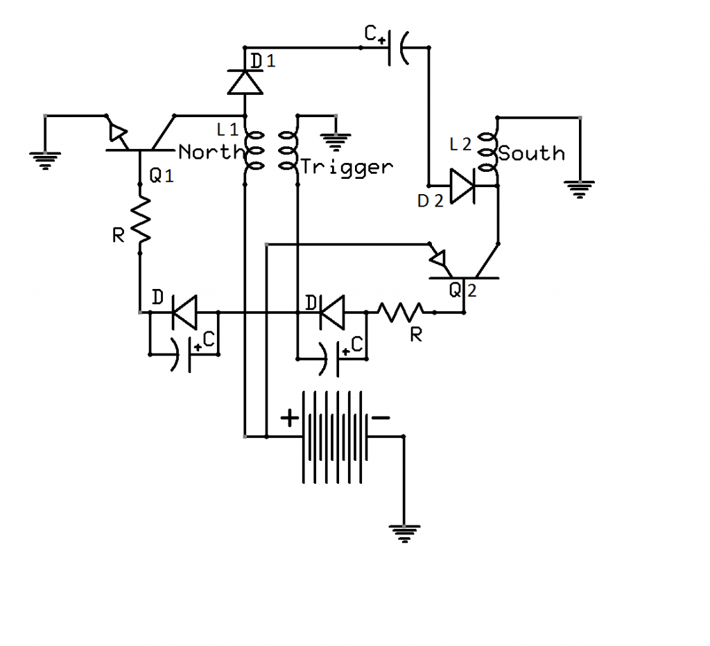
          If a coil is pulsed with neg energy like from an npn transistor the coil takes on an overall neg charge----the coil ionizes the air around it, even to a small degree depending on the energy applied.

          Since the coil is neg charged the ionized air will be pos "opposites attract"
          therefore when the magnetic field of the coil collapses it will bring in a pos charge----pos bemf.

          And like wise if a coil is pulsed with pos energy like from a pnp transistor the coil takes on a pos charge and the air around it will be neg and its bemf will be neg.

          All bemf collectors that I have seen confirm this supposition, even transformers.

          A transformer has what is called reactive power, reactive power is nothing but bemf fighting the system.

          When a coil is pulsed (we will use an npn transistor since its more widely understood) the coil becomes neg on the end faceing the transistor then when the bemf hits the coil (after the pulse is off) the end of the coil facing the transistor becomes pos.
          The reason being the bemf collapsing into the coil has a pos polarity.

          Why is the buck and boost converter so important,,, because they show this polarity change.

          The buck convertor increases amperage at the expense of voltage.

          The boost converter increases voltage at the expense of amperage.

          Voltage without amperage does us little good and so the same with amperage without voltage............we have to increase both to get overunity.

          Personally I would like to see us put our differences aside and bust this wide open.
          We can do it
          Its going to happen
          Its a snowball thats gaining momentum

          Lets say we have two ion clouds that are of opposite polarity separated so as to not allow recombination.
          We take a coil and place in the clouds then use the magnetic field of each coil to align and collect electrons and positrons from each,,,,,,,,,,then we have a source to draw from besides our battery's.

          When a coil is negatively energized it takes on an overall neg charge then when the magnetic field collapses it takes on a pos charge as the pos bemf courses through the wires but what if the core were not allowed to take the pos, what if it stayed neg,,,,,,,,,,,,more pos charge would be drawn in.

          Just the fact that pos and neg ion clouds form around electrodes of an air purifier should alert each of us that both have to be collected to reach overunity, both pos and neg charge.

          What happens when pos and neg charges meet,,,,you get a release of energy,,,,,,,,,,heat, light ect. then the charge becomes neutral, disappears, it really doesnt disappear it becomes neutral and fails to register on our meters.

          The ionosphere is pos............the earth is neg.............the area in between is neutral (combined charges) we have to split the charges to collect them, both of them.
          Half of the Answer is knowing the right Question

          Comment


          • #6
            transformers

            Hi Dave, so reactive power is just bemf captured?
            I hook 2 in series with the output of the secondaries to charge caps, while the primaries act as conductors, which run the load.
            The battery lasts the same amount of time , weather I charge and discharge the caps or not.
            Not all transformers work .
            Sorry just gettin carried away.....
            artv

            Comment


            • #7
              Q&A

              Originally posted by Dave45 View Post
              I surely dont want to get in the middle of this or any other argument but I have been studying this for a long time and have yet to see any other schematic that shows how to collect both neg and pos bemf in the same circuit.

              Except Matts

              I have this theory dont we all, that opposites attract and like polarities repell, =====I guess thats not a theory but a law.

              If a coil is pulsed with neg energy like from an npn transistor the coil takes on an overall neg charge----the coil ionizes the air around it, even to a small degree depending on the energy applied.

              Since the coil is neg charged the ionized air will be pos "opposites attract"
              therefore when the magnetic field of the coil collapses it will bring in a pos charge----pos bemf.

              And like wise if a coil is pulsed with pos energy like from a pnp transistor the coil takes on a pos charge and the air around it will be neg and its bemf will be neg.

              All bemf collectors that I have seen confirm this supposition, even transformers.

              A transformer has what is called reactive power, reactive power is nothing but bemf fighting the system.

              When a coil is pulsed (we will use an npn transistor since its more widely understood) the coil becomes neg on the end faceing the transistor then when the bemf hits the coil (after the pulse is off) the end of the coil facing the transistor becomes pos.
              The reason being the bemf collapsing into the coil has a pos polarity.

              Why is the buck and boost converter so important,,, because they show this polarity change.

              The buck convertor increases amperage at the expense of voltage.

              The boost converter increases voltage at the expense of amperage.

              Voltage without amperage does us little good and so the same with amperage without voltage............we have to increase both to get overunity.

              Personally I would like to see us put our differences aside and bust this wide open.
              We can do it
              Its going to happen
              Its a snowball thats gaining momentum

              Lets say we have two ion clouds that are of opposite polarity separated so as to not allow recombination.
              We take a coil and place in the clouds then use the magnetic field of each coil to align and collect electrons and positrons from each,,,,,,,,,,then we have a source to draw from besides our battery's.

              When a coil is negatively energized it takes on an overall neg charge then when the magnetic field collapses it takes on a pos charge as the pos bemf courses through the wires but what if the core were not allowed to take the pos, what if it stayed neg,,,,,,,,,,,,more pos charge would be drawn in.

              Just the fact that pos and neg ion clouds form around electrodes of an air purifier should alert each of us that both have to be collected to reach overunity, both pos and neg charge.

              What happens when pos and neg charges meet,,,,you get a release of energy,,,,,,,,,,heat, light ect. then the charge becomes neutral, disappears, it really doesnt disappear it becomes neutral and fails to register on our meters.

              The ionosphere is pos............the earth is neg.............the area in between is neutral (combined charges) we have to split the charges to collect them, both of them.

              Hello Dave and ART

              I am a state of shock at these few words you wrote about charges. I have never heard anything like that before. This is the answer to my question I asked a while back and now I see why it was not just a snap or super easy explanation.

              It sounded like you were saying that by building a pos and neg generator arrangement using coils these both having clouds of energy could be kept running in one direction never reversing direction or collapsing.

              Your statement "WHAT IF IT STAYED NEG?" You got me. Maybe place another coil into the double whamie neg pos gen field?

              Or figure a way to grab some of that cloud up?

              Using Another coil placed in such a way that neither the neg field coil nor pos field coil were canceled out but rather a balanced draining?

              That is what I got so far. That stuff tickles my imagination, give me more.

              Mike
              Last edited by BroMikey; 07-09-2014, 07:45 PM.

              Comment


              • #8
                Gimmy Free Energy Man, Please

                Originally posted by Dave45 View Post
                Im in the process of moving my shop
                got my bench built, Im going to be moving my power supply's and meters today, finally.
                My next project

                Matts bipolar cap charger, Iv been studying it for a long time, Matt put the icing on the cake when he posted the schematic.
                I have some idea's to enhance the circuit--------split the aether.
                Get ready for free energy my friend.
                I can't wait to see the new shop set up. I think it is important to draw attention to your statement concerning the coil ION fields.

                Mike
                Last edited by BroMikey; 07-09-2014, 07:43 PM.

                Comment


                • #9
                  Cores

                  Dave45 Wrote:

                  "When a coil is negatively energized it takes on an overall neg charge then when the magnetic field collapses it takes on a pos charge as the pos bemf courses through the wires but what if the core were not allowed to take the pos, what if it stayed neg,,,,,,,,,,,,more pos charge would be drawn in."


                  Hi Dave

                  I guess the first time I read this I missed something. It seems like you are talking about a CORE MATERIAL that would repel the positive.

                  Mike

                  Comment


                  • #10
                    Originally posted by BroMikey View Post


                    Hi Dave

                    I guess the first time I read this I missed something. It seems like you are talking about a CORE MATERIAL that would repel the positive.

                    Mike
                    Not repel the positive but bring in more pos

                    If opposites attract and a neg charged coil brings in pos energy when the magnetic field collapses you get an equal but opposite reaction.
                    But if the core of that coil were charged neg then the flow of pos energy would continue to flow into the coil, trying to neutralize the neg, all energy seeks neutral charge.
                    If it didnt we would not be able to live on this planet, the atmosphere would be so electrically volatile no life could exist.

                    Lets look at your circuit in an unconventional way pun intended.
                    Look at the circuit from electron flow and not conventional view.

                    Electron current flows from The neg side of the battery through the npn transistor into the coil building the magnetic field of the coil, when the magnetic field collapses the energy flows back the opposite direction back towards the transistor but the transistor is off so it takes the path through the diode into into the pos side of the cap and ultimately the battery.

                    Now when the transistor was conducting notice the neg energy did not go through the diode, because of the diodes orientation, but the bemf did.

                    This show us the bemf is of a pos polarity-----------

                    Your circuit is essentially a boost converter now study the buck converter its bemf is neg, the energy in the buck flows from pos to neg because of the pnp transistor and the same reaction occurs.
                    Last edited by Dave45; 07-10-2014, 03:09 AM.
                    Half of the Answer is knowing the right Question

                    Comment


                    • #11
                      Buck Booster combination

                      So this all sounds like you are saying that a buck circuit might keep a booster circuit neg at the coil and maybe the same thing could occur at the pos side of the buck using a boost.

                      The two opposites could be operated together to open a window of energy to flow in from another unknown source.

                      Mike

                      Comment


                      • #12
                        The two opposites could be operated together to open a window of energy to flow in from another unknown source.
                        The source is not unknown, its the atmosphere we live in.
                        But it has to be ionized.
                        Half of the Answer is knowing the right Question

                        Comment


                        • #13
                          Okay Known Source

                          Dave Wrote:
                          Lets say we have two ion clouds that are of opposite polarity separated so as to not allow recombination.
                          We take a coil and place in the clouds then use the magnetic field of each coil to align and collect electrons and positrons from each,,,,,,,,,,then we have a source to draw from besides our battery's.
                          [/COLOR]


                          I am re-reading.

                          It does sound like you are saying that two ion fields pos and neg would be lined up with a "THIRD COIL" for collection and maybe a fourth? One collection coil aligned with each of the buck and boost ion generators.

                          Having both ion clouds of pos and neg would require some doing like building a buck circuit with just any coil? Or should a Bedini coil work? I have one all wound.

                          I am under the impression that whatever the coil arrangement it's mass is important. To short or to long will not be optimum.

                          As far as I am concerned I would stay with the twisted wire Bedini style coil and wind one up the other way and then I would have both fields using my 4 channel 14awg wire with 20awg trigger to set both coils in sync.

                          All I need is a south wound coil and some PNP transistors as well as the base triggering parts. Next why not do away with the simpleton base triggering diode and cap and go with a more sophisticated circuit with a lot more control?

                          Mikey

                          Comment


                          • #14
                            Solid State Osc

                            Here is a variation of the SG Osc Laserhacker said it himself.

                            http://www.overunity.com/10179/joule.../50490/image//

                            Notice the cap and diode positive triggering for self oscillations without digital processors. The diode and cap both have resistance and form a tank for finding the resonant frec.

                            Of course the only difference is the coil.

                            Mike

                            Comment


                            • #15
                              Notice the cap and diode positive triggering for self oscillations without digital processors. The diode and cap both have resistance and form a tank for finding the resonant frec.

                              Youv been holding out

                              Take it a little further where's the double pos triggering

                              The bemf from the coil being pulsed is the second pos trigger
                              Half of the Answer is knowing the right Question

                              Comment

                              Working...
                              X