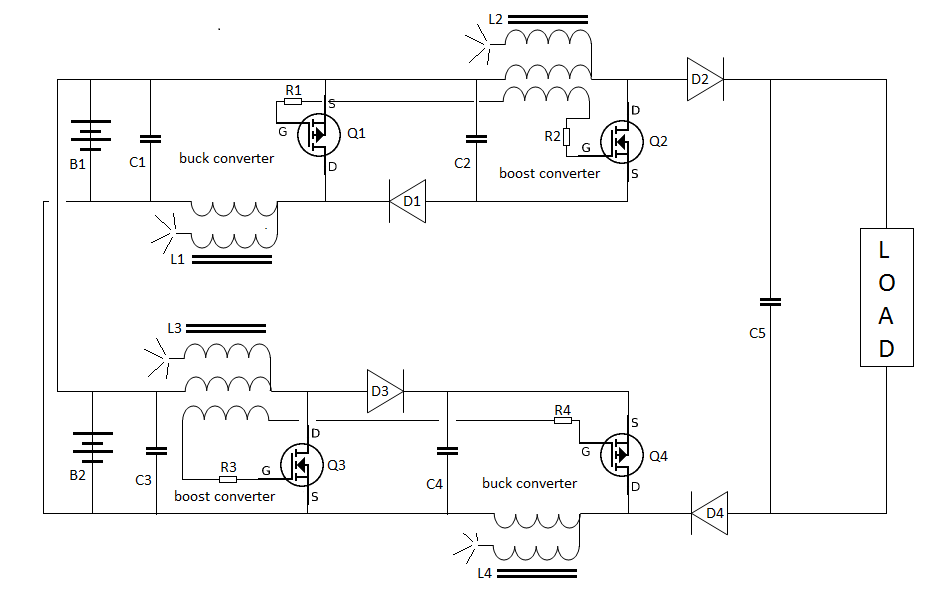
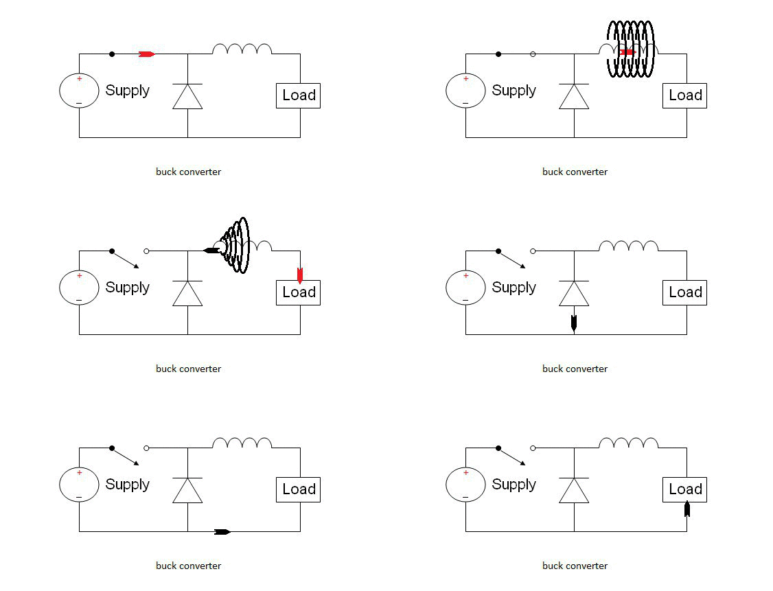
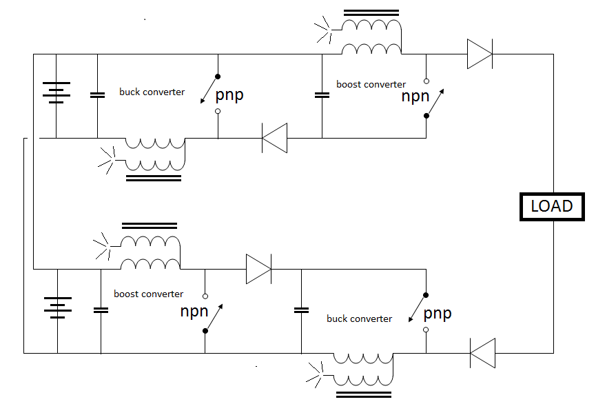
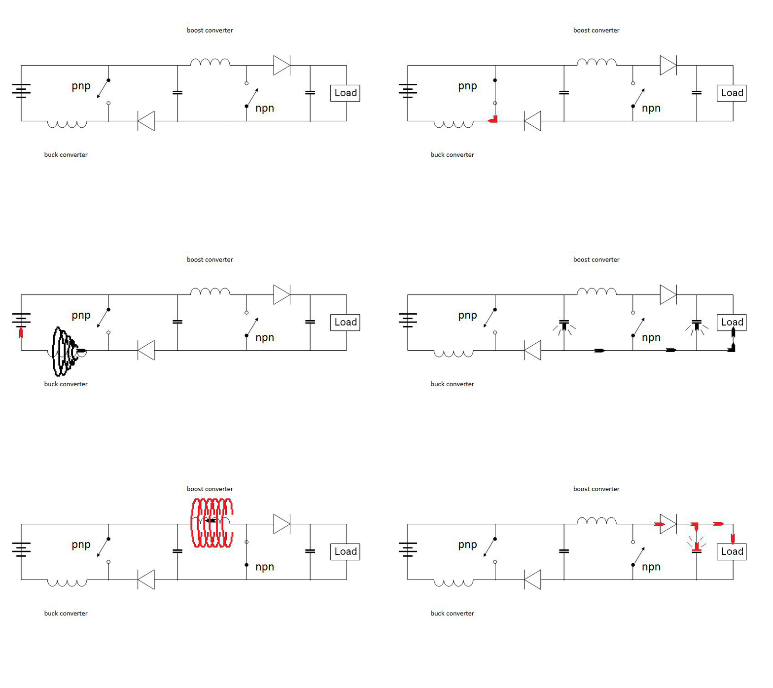
Mike if you add these pics to your science page then right click the image select copy image location you can use the insert image button at the top of the post reply page to insert the image directly into the forum without using up your allotted forum bytes.
Announcement
Collapse
No announcement yet.
Sssg Osc Variations Bedini 2x Plus
Collapse
X
-
Woe Dude
Dave you must be a mind readerOriginally posted by Dave45 View PostMike if you add these pics to your science page then right click the image select copy image location you can use the insert image button at the top of the post reply page to insert the image directly into the forum without using up your allotted forum bytes.
I was sitting here all week wondering how you did that with pictures opening up across the whole page. I'de be thinkin "maybe I should ask?"
I looked for forum help but didn't see anything.
Now I see what you mean "COPY IMAGE LOCATION" gotcha that is to easy.
Mike
Comment
-
Energy Pumping
@Dave
I like the Bedini Patent called the energy pump but he didn't incorporate any coils in that one because it was never intended for high COP's, just a basic pump to run motors and loads more efficiently.
I like the pumps with coils on them. I see you said someone else can up with coils that had one end unconnected. Did you ever get a change to draw up more than a block diagram for this last circuit with sections in it?
I guess it would be two of the singles but that would mean each of the four coil needs to be trifilar. So this would be one coil in one of the four quadrants should have three wires, one going to the trigger, #2 as the powered coil and #3 hooked on one side to the powered coil.
Get something more specific drawn up next time around and maybe that one is the one I should build. One of my big issues is that I don't know much about the coils. The circuit is very easy and can be put together in a few moments with the exception of trading in and out caps and resistors for tuning.
Everywhere around the web you hear 130 turns or 130 feet or as high as 500 feet. Bedini has his patent tube oscillators at about 30-40 feet.
Mike
Comment
-
Hey Mike
The thread works for me, I havent went any further with the circuit design yet but I will label the components soon to start a build.
I dont have any component values as the circuit is still in the dream stage
Actually the buck and boost converter's have been around for a long time so finding component values to start should not be hard to find, Iv used google to search for both and there are plenty to study.
There are alot of ic's and I have studied alot but have decided to stay away from them and use the Kiss method. Iv notice when an ic is used everyone is studying the ic instead of the coil reactions.
An arduino setup would be ideal for gate operations but Im not that advanced so Im going to take the easy way out and set it up with a feedback winding as Matt suggested.
I would like to stop here and give everyone and invite to help on this project, no matter how skilled or unskilled you are, you cant be any more of a circuit rookie than me
Even if we dont get free energy we are going to build one heck of a DC to DC converter.
Im going to build solenoid type coils, Matt said to stay away from toroids, I think no matter how you wind or on what ferrite is the way to go because of the switching frequencies.
Guys I think if you want to wind on toroids or e cores or on a banana thats great and wiil be very interested in your results.
If you want to twist your wire or lay it side by side or anyway you want we would like to see the results.
I have some idea's on coil winding that I want to try but winding our coils the way each of us wants will give diversity to the build and we should encourage that.
Im going to separate the coils for reasons Iv stated but if you want to wind every coil on the same core I would be very interested in the results.
It will be next week before I can order components so in the meantime Im going to search and set up a parts list.
Cores can be gotten off ebay , transistors are the next on the list, Im searching for a complementary pair that will work, any Idea's are surely welcome.
Lets buildHalf of the Answer is knowing the right Question
Comment
-
Disclaimer; If you do not know how to handle electricity do not build this circuit, if you do I/We are not responsible for your safety. This circuit will put out enough voltage and amperage to kill, I/We dont advise you to build it. Do not build this circuit if you dont know what your doing.
This is a capacitive discharge circuit and is very lethal.
Just because this circuit is DC do not be fooled you may touch 12 volts but this is going well above 12 volts and is pulsed, do not touch and always remember to discharge the caps.Half of the Answer is knowing the right Question
Comment
-
Iv labeled the components, please proof read.
If anyone has an idea on a different way to hook up the battery's please reply, this was a quick layout when I joined the two circuits and not alot of thought was put into it.
In future builds the diodes could be replaced with switches but for now Im going to keep it simple.
If anyone has suggestions on the gate feeds please reply.
 Last edited by Dave45; 07-27-2014, 04:58 PM.Half of the Answer is knowing the right Question
Comment
-
UFO you should like this circuit its about as asymmetric as it gets
If any of the more experienced would like to give starting component values it would be appreciated.
I know its dependent on inductance values of the coils.
I need to buy an inductance meter, any suggestions, Im looking at this one
Amazon.com : Atlas LCR45 Impedance Meter : Everything ElseLast edited by Dave45; 07-27-2014, 05:00 PM.Half of the Answer is knowing the right Question
Comment
-
Circuit Evolution
Hey Dave nice one on circuit drawings that wooda took me all day to make.Originally posted by Dave45 View PostUFO you should like this circuit its about as asymmetric as it gets
If any of the more experienced would like to give starting component values it would be appreciated.
I know its dependent on inductance values of the coils.
I need to buy an inductance meter, any suggestions, Im looking at this one
Amazon.com : Atlas LCR45 Impedance Meter : Everything Else
Really nice work. I also found these poor boy meters that are stark naked out of the box lcr meter | eBay
I am a cheap-o when it comes to buying cause i might burn up a $200 rig learning how to work it.
Most of the time the boxing up costs more money than the inter core of the circuit.
Some of these circuits make light work of measuring semi's and I won't need
a magnifying glass to see the readout.
It seems like to me that a solenoid/Bedini wind and black sand core would suit me fine. I see that black sand high frec core material right on ebay.
black sand | eBay
Then Throw a little quick epoxy into the sand and stir.
quick epoxy | eBay
Also these dc to dc converters can produce fairly high voltages with substantial amounts of current sufficient enough to put this model well beyond safety limits for a novice.
Just because we are following the simple approach to triggering not using IC chips does not lower the potency of the power levels achieved by these converters.
Caps rated at 220vdc operating along side 130' foot to 500 turn coils in a buck boost array might surprise a beginner if they are only use to 12vdc battery switches and so forth.
The goal here is to take these circuits beyond a "proving it works" "toy soldier" stage where parts end up at the bottom of the pile afterword with only memories of how cool it was.
It is time to go to the next level. I am so sick of toy projects I could screem To me if I can't take a simple circuit idea like the cap dump and make it do some sort of beneficial task then I call it a cute experiment but worthless in the practical world.
If these coils have a target inductance that would be better because I am thinking of using 14awg wire. The reason of course is that a coil of thinner wire will reach the inductance figures faster than the thick wire.
Short coils are unstable for the generation of ION clouds over wire.
Mike
Mike
Comment
-
Gate triggering
Hi DaveOriginally posted by Dave45 View PostIv labeled the components, please proof read.
If anyone has an idea on a different way to hook up the battery's please reply, this was a quick layout when I joined the two circuits and not alot of thought was put into it.
In future builds the diodes could be replaced with switches but for now Im going to keep it simple.
If anyone has suggestions on the gate feeds please reply.

What would be the purpose of replacing the diodes with switches? Would they be fet's?
@ALL
As far as triggering the bases of the existing fet's I have always used coils, diodes, resistors and caps to form some sort of a tank circuit that resonates.
So to find a desirable oscillation point in this simplistic layout I will be using variable resistors for openers. Cap values would be switched out manually just as diodes. Germanium and silicone diodes have different characteristics but silicone is the only diode type I have witnessed for base triggering.
There are many ways that a diode can form a tank circuit with coils containing a degree of capacitance. By a tank I mean an oscillation with resonant qualities suitable for turning on and off a transistor. All caps and coils exhibit one frequency known as a "TANK CIRCUIT" and can be easily calculated.
Most of you are well acquainted with today's modern "Tank" calculators.
Back in 1971 when I studied circuits all 555 timer type chips were built LONG HAND. This meant we had a slide-rule to do measurements. Things are easier now.
My classmates built a TV that took up an entire kitchen table that was built without the cheater IC's. This required us to do the math for every bias and so on down the line using transistors, caps and diodes.
Without the use of a modern IC a transistor Radio back then that we all aspired to build was quite large and costly to make. Especially if you wanted stereo with quadraphonic's.
I am giving you a little history on "WHY" Why in the world would I be making all of my circuits free of IC's. Well because it is to easy to make mistakes thinking you have it right when you don't really know what the IC is doing because you didn't build it or understand everything that it is doing.
Use of IC's can come after the desire effect is known.
IC's need opto's to protect them and on we go till the circuit becomes more accurate and complicated. This is fine.
Getting all four transistors to oscillate close to the same as it's counterpart is easy, but finding the optimum operating parameters through fine tuning is most important.
Naturally tuning is done in this case to charge a CAPACITOR as quickly and as efficiently as possible. It has been pointed out that expanding and collapsing magnetic fields and their ION energy clouds need to be collected to make the circuit 100 percent efficient.
We all know what that means, if a circuit can be made to operate at 100 percent efficient with all of it's losses known to standard electrical engineering designs then extra energy is already present.
MikeLast edited by BroMikey; 07-28-2014, 01:49 AM.
Comment
-
Hey MikeWhat would be the purpose of replacing the diodes with switches? Would they be fet's?
Yea fets could replace the diodes for better conduction with lower losses but for now Im going to use diodes.
Guy's Im gonna be out for about a week.
This is gonna set me back but I'll try and catch up.
Keep on Keepen on
daveHalf of the Answer is knowing the right Question
Comment
-
Hey Guys everything went well.
Mike couldnt get the vid on your last post, may have been removed.
Ready to rumble
https://www.youtube.com/watch?v=6_39wbGIJ_IHalf of the Answer is knowing the right Question
Comment
-
Lets look at it in stages
First stage is just a buck converter it loads up the neg side of C2,
Stage 2 is a boost converter but it releases the neg side of C2 and we get a capacitive discharge through L2,
The bemf from L2 is pos and runs through D2 into C5 and the load.
Stage three is a boost converter that loads up the pos side of C4
Stage 4 is a boost converter it releases the pos side of C4 and we get a capacitive discharge through L4,
The bemf from L4 is neg and runs through D4 into C5 and the load.
Its just a pump
But incorporates a capacitive discharge on both sides.
Last edited by Dave45; 08-01-2014, 02:44 PM.Half of the Answer is knowing the right Question
Comment


Comment