Announcement

Collapse
No announcement yet.

Sssg Osc Variations Bedini 2x Plus

Collapse
X
 
  • Filter
  • Time
  • Show
Clear All
new posts

  • #31
    Running the gates with arduino or the like would be the way to go, stage one could be ran at twice or even triple the frequency of stage two this would increase the capacitive discharge through L2

    The same for stages three and four.

    Stages one and two are coupled to work alternately and the same for three and four, but stages one and two are not coupled to three and four and can work independently.
    Half of the Answer is knowing the right Question

    Comment


    • #32
      Doin It Up Right

      Originally posted by Dave45 View Post
      Lets look at it in stages
      First stage is just a buck converter it loads up the neg side of C2,
      Stage 2 is a boost converter but it releases the neg side of C2 and we get a capacitive discharge through L2,
      The bemf from L2 is pos and runs through D2 into C5 and the load.

      Stage three is a boost converter that loads up the pos side of C4
      Stage 4 is a boost converter it releases the pos side of C4 and we get a capacitive discharge through L4,
      The bemf from L4 is neg and runs through D4 into C5 and the load.

      Its just a pump
      But incorporates a capacitive discharge on both sides.

      Absolutely Dave we gotta be doin it up right and get some of the free stuff Great to have you back and I hope all is well.

      Your circuit keeps sprouting a set of new legs. She is a beaut

      I wouldn't say it was a circuit worth dying 4 but pretty good anyway.

      I wonder if I tried it use like say 40 awg size wire coil to make it easier to start testing. I just put my other circuit together with my eyes closed but this one will require I get in close.

      Ready ta Rumble? Of course, you know how it is with this new set of chains so far all I have needed was a fly swatter but now with this new circuit it looks like I will have to dig up the real hardware.

      Mikey
      Last edited by BroMikey; 08-01-2014, 07:40 PM.

      Comment


      • #33
        For some reason I cant access the last page of this thread
        Half of the Answer is knowing the right Question

        Comment


        • #34
          Manetic energy Amp

          Originally posted by Dave45 View Post
          For some reason I cant access the last page of this thread
          Hey Dave the site attacks up. Here is that magnetic energy amp link again

          https://www.youtube.com/watch?v=Wrcb5WRu_cw

          Coils and magnets

          Mike

          Comment


          • #35
            For some reason I cant seem to access the last page in this thread, posting from the first page.
            Half of the Answer is knowing the right Question

            Comment


            • #36
              Generation Circuits

              Originally posted by Dave45 View Post
              Running the gates with arduino or the like would be the way to go, stage one could be ran at twice or even triple the frequency of stage two this would increase the capacitive discharge through L2

              The same for stages three and four.

              Stages one and two are coupled to work alternately and the same for three and four, but stages one and two are not coupled to three and four and can work independently.
              hey Dave can you C this post? Maybe this part of the site in malfunctioning?

              Are you seeing the link I posted days ago?

              For some reason our posts are being interfered with. I kind of expect some problems to arise on this site. I goes out from time to time, hacking is rampid
              these days.

              Mike

              Comment


              • #37
                coil pulsing

                Double Joule thief By Dave45

                Comment


                • #38
                  Sohei Thoth dual Joule

                  Double Joule Theif

                  https://www.youtube.com/watch?v=lPW53ExXFcg

                  In 2013 youtube user Sohei Thoth

                  Also a dual one by humm let me think


                  Mike

                  Comment


                  • #39
                    Thats a cool setup, really liked his charging circuit.
                    He showed the schematic, alot of people dont.
                    He's using two boost circuits, everyone concentrates on the voltage side and neglects the amperage side.......big mistake.
                    But still very cool

                    just need to get rid of that solar panel
                    Last edited by Dave45; 08-05-2014, 11:33 PM.
                    Half of the Answer is knowing the right Question

                    Comment


                    • #40
                      Anything you can do on the pos rail you can do on the neg rail, boosting voltage and amperage.
                      Im not sure if a zener diode will work like this but a zener will conduct in reverse until a specified voltage is reached and then clamp, could we us a zener to pulse charge the battery.
                      Last edited by Dave45; 08-06-2014, 03:04 AM.
                      Half of the Answer is knowing the right Question

                      Comment


                      • #41
                        zener Circuits

                        Originally posted by Dave45 View Post
                        Anything you can do on the pos rail you can do on the neg rail, boosting voltage and amperage.
                        Im not sure if a zener diode will work like this but a zener will conduct in reverse until a specified voltage is reached and then clamp, could we us a zener to pulse charge the battery.
                        Yeah Zener circuits Dave I need to see more.

                        The zeners and how to use them have been plaguing me for awhile. I mean I have some 5-7 watt zeners but where would be a good place to use one is the question.

                        Mike

                        Comment


                        • #42
                          Pulsing a battery

                          Originally posted by Dave45 View Post
                          Anything you can do on the pos rail you can do on the neg rail, boosting voltage and amperage.
                          Im not sure if a zener diode will work like this but a zener will conduct in reverse until a specified voltage is reached and then clamp, could we us a zener to pulse charge the battery.
                          Wait a minute Dave I see what you mean now.

                          You have one battery like Johan and you want to pulse charge the same battery that is running the circuit. well let's put it this way.

                          The first frequency hitting the battery do a tiny boost in efficiency and the second harmonic brings it up just a little more but that 3rd one really ties the knot.

                          120 degrees around the circuit of a three phase core such as an alternator of a car. circular shape no big deal. You kick the ball every 120 degrees to the outside till the swirling action is produced.

                          Now there is your tornado.

                          3 phase systems are known to be much more powerful even in standard EE terms.

                          Did you ever take a look at Peter L. toroid motor?

                          Also take a look at the 3 phase toroidal wind Johan uses for pulse charging his daughters kiddy car battery.

                          It use approx 30 turns each 20awg silver coated teflon solid magwire over top of the 16awg silver coated first layer. Some thing like 100-108 turns I think it is for the secondary.

                          Remember the primaries are on top and short pulsing only 12vdc at a few miliamps. The secondary is in mutual inductive contact only with these pulsing primaries when straight dc is sent through the secondary to battery or HHO cell same thing.

                          The voltage and amperage running through the secondary to the battery is turned down so low that it only slightly raises the voltage of the batteries setting voltage.

                          Now MUMU nature has her chance to make a different. She can't do diddly if we crank the power up to boil the battery so we turn it down to only very very low crawl.

                          Next we fire up our 3 primary coils creating a swirling Aether vibration looking for a perfect window of operation to resonate with MA

                          Tesla hid things and his terms for resonance and EE term don't mix.

                          You gotta follow the music or you end up with what we have now, Nothing.

                          Mike
                          Last edited by BroMikey; 08-06-2014, 02:47 AM.

                          Comment


                          • #43
                            Super Joule Ringer Looper


                            Mike

                            Comment


                            • #44
                              SSSG Variant


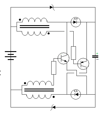
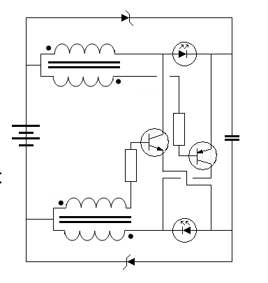
                              These drawings are the evolution of John Bedini's Oscillator circuits. The new circuits will soon be collecting enough to be practical.

                              Mike

                              Comment


                              • #45
                                These drawings are the evolution of John Bedini's Oscillator circuits.
                                Yea bemf collection circuits.
                                The complementary pnp for the 2N3055 is MJ2955 I think I have some will look tomorrow
                                Half of the Answer is knowing the right Question

                                Comment

                                Working...
                                X