Announcement

Collapse
No announcement yet.

S.e.r.p.s.= Dynaflux+flyback Switching

Collapse
X
 
  • Filter
  • Time
  • Show
Clear All
new posts

  • S.e.r.p.s.= Dynaflux+flyback Switching

    I am starting this thread for those who wish to study the way Jim Murray and Paul Babcock arrived at their new technology.

    The first thing we have all done with Tesla is to go read his patents.

    Both of these men have worked in the electrical field their entire lives just like Tesla did. Both men know that Tesla offered more than the current laws in schools today teach.

    Paul's flyback switching is very similar to the attributes of a mechanical switch and is a very important piece of the puzzle.

    The Dynaflux theory of operation should be studied equally as much.


    https://docs.google.com/viewer?url=p.../US4780632.pdf


    Also when studying the work of these men with their patents, PRIOR ART should also be reviewed. This is a tab we find on patents. It says PRIOR ART.

    Prior Art is most often other related patents that the inventors followed generally earlier in the century and whether they followed the earlier patents intentionally or unintentionally the patent office will identify and put all of the same types of patents together.

    There is much to learn from PRIOR ART and even if we only read the inventors patents that are based on a life's work, we may not get through all of the material as quickly as we might think.

    Let it take time.

    If we sort through Murray III patents and P. Babcock patents we might understand some of it in a few months of studying.

    This is one place to start.


    Patent US20110157942 - Controllable Universal Supply with Reactive Power Management - Google Patents

    Remember that the flyback switching without understanding the Dynaflux would be an incomplete understanding of the way the SERPS operates.

    Both men's patents need to be studied so that we can see how the SERPS works and these few articles I have included represent only a small portion of each mans work.

    Mike
    Last edited by BroMikey; 08-18-2014, 05:18 AM.

  • #2
    Images from Patent


    These are just a few of the complete collection of patent images.

    Mike

    Comment


    • #3
      Waveform

      Comment


      • #5
        Analysis of SERPS TECH

        For those of you who like to build the SERPS unit and have not had as much time as you would like to put all of the pieces together, I am attempting to set general perimeters for it's operation based on the video facts by the inventors.

        Also Patent information.

        If I say anything that is not correct please be free to update us on that information.

        It is my understanding that this process that has evolved into a solid state resonant switching device called the SERPS unit originally used windings like in a generator motor but now uses winding in a standard transformer.

        The Dynaflux and Flyback switching both with their respective creators each taking many years to perfect their separate techs and the main goal in each instant was to recover some of the waste energy in these systems and recycle that power for re-use.

        At first glance the DYNAFLUX looks very simple yet the rotor is built far different than our standard rotors today. James Murray III used recovery circuits to explore and perfect in his effort to increase efficiency.

        Paul Babcock has the FLYBACK ENERGY SWITCHING corporation and has searched for ways to recover energy from motor windings in his way.


        The SERPS is a resonant device that does not center around standard resonance. Everyone who has worked with alternative energy motors should know that motor windings and switching are arranged to catch the rebounding waves of energy sent out by the switch to perform the motoring task.

        This energy like all waves are sent at whatever frequencies and the circuits are designed to sense their levels, phase or values so proper timing to recover the intermittent reoccurring fluctuation can be maintained.

        It seems to me that half of the word "DYNA" in the name DYNAFLUX sounds similar to DYNO and while I don't believe the DYNAFLUX tech uses brushes like in a standard alternator it may be that the rotor changes causes a DYNO like effect.

        I want to stress that I have not had time to thoroughly investigate all of the Patent details and am speaking purely speculatively based on what I know about Tesla and his use of the DYNO.

        You see a big challenge today is for inventors to come up with a circuit and systems that use the standard induction motors already in use today and we know from history that Tesla used both induction motors and Dynomotors.

        Even a beginner may know the advantages and disadvantages of the sparking commutator found with the use of a Dynomotor. I think we still have some of those very old generators around the shop here for cars and tractors when brush type generators were still used eariler in the 20th century. They motor resemble a starter motor with it's elongated shape.


        This brings use to how some inventors have used various motor generator schemes in conjunction with the recovery circuits to learn by experience what works and what doesn't. And when all of the math seems correct and the unit is built, 99 percent of the time it is found that the theoretical math equation was not the full answer.


        This can be seen by the many many prototypes that needed to be built in any new tech as the phenomena has not been fully explored and documented.

        Jim Murray has a rotor there that looks like it wobbles so to speak yet perfectly balanced of course.

        I need to leave for now and will be back to offer you what comes to mind. Also remember that I am not an EE and am only offering my thoughts more from a historical view.

        I am approaching 60yrs and when I see the video and I hear the name ERIC, I see a young man who is using his talent to build circuits as specified by the inventors, thinking how nice that is to use the energy of the younger to perform that pain staking circuit building task. Keeping up with all of the new design topologies and chips in and of itself in a full time job.

        Without help and first understanding how the SERPS evolved from PRIOR ART this is an insurmountable task.

        The standing waves in any circuit can be recovered but if we are only going for frequency waves then we are bound for disappointment.

        Mike
        Last edited by BroMikey; 08-18-2014, 07:57 PM.

        Comment


        • #6
          Switched reluctance Multi-Rotor

          http://s3-us-west-2.amazonaws.com/le...l/00000001.png


          mike

          Comment


          • #7
            Controllable Universal Supply with Reactive Power Management

            I took out a few minutes of the day to look at Paul Babcocks Reactive Power Management patent and I find these waveforms very interesting.

            In fact the last diagram is the one I will post first that most resembles the demonstration video wave form. Of course all of the management circuits operate in quadrants or divisions of four.

            Patent US20110157942 - Controllable Universal Supply with Reactive Power Management - Google Patents

            This is the flyback switching.

            Also a battery charger flow diagram gives us some idea how the system controls the reactive power. First the waveforms.

            The last waveform is posted first using the lowest power level, next is 1-4 operating at higher power levels.


            And here is the Battery Charger


            I didn't get time to zero in on the text for this portion of the patent but I need to.

            Mikey

            Comment


            • #8
              Reactive Power Patent Text

              Here is a starting point for understanding the goal for REACTIVE POWER MANAGEMENT.


              methods involve a controllable supply adapted for controlling switch phasing and pulse width


              The Patent Text is in Dark Red.

              The opening statement says the goal is to manipulate phasing and PWM.

              Next we read what phasing and PW controls do..................

              to regulate reactive power drawn from the source


              Also we read what happens when these controls are used

              to qualize power in adjacent quadrants of a sinusoidal source voltage waveform

              And that these equalizing controls.....................


              to regulate reactive power drawn from the source


              So as the opening statement reactive power is controlled by using a circuitry that operates in quadrants, can move the phase and can accurately control pulse width.

              All though there are many other lines of text in this patent that need to be added we have a basic idea where to start.

              It sounds like to me phasing plays a big roll by equalizing some of the counter EMF with power recycling. We all know that pulse width does good things to control levels but not everyone has much experience with controlling phase and PWM.

              This opening statement means a lot to the experimenter because he now can begin to setup circuit designs that can handle 4 separate channels, one for each quadrant. Also these channels most likely will possess advanced micro processing abilities to perform such a complicated task.

              Mike

              Comment


              • #9
                SERPS-Supervisory Circuit Topology

                The Patent writing is in "Dark Red" below is a break down of the circuit sections that operate together to perform a task. It focuses on the AC sine wave being rectified and how the circuit can connect parts of that voltage value up to a load. Also the circuit will chose a PULSE WIDTH to control power levels control by using feed back information.

                The feed back computer will control the delay time for phase control as well as PW collecting data in quadrants all done to EQUALIZE POWER.


                Patent US20110157942 - Controllable Universal Supply with Reactive Power Management - Google Patents


                1. A method of managing reactive power, the method comprising:
                rectifying a substantially sinusoidal source voltage waveform from a source to a rectified voltage node;


                [providing a switch arranged to selectively couple the rectified voltage node to a load;]


                [determining a pulse width value for turning on the switch to deliver a desired average power to the load;]


                [receiving information about relative power drawn from the source during adjacent quadrants of the source voltage waveform;]


                [determining a switch turn on delay time to substantially equalize power between adjacent quadrants of the same polarity;]


                and,
                [controlling the switch during at least two successive half cycles of the source voltage waveform according to the determined switch turn on delay time.]


                Have fun it's a beauty

                Mike


                Last edited by BroMikey; 08-21-2014, 07:42 PM.

                Comment


                • #10
                  Flyback Switching

                  Condensing by removal of repetitive phases Of Patent


                  Switch Phasing and Pulse Width to Regulate Reactive Power


                  Patent US20110157942 - Controllable Universal Supply with Reactive Power Management - Google Patents


                  comprising controlling a reverse electromotive force associated with rapid turn off of the switch, and capturing inductive energy stored in the load when the switch disconnects the load from the rectified voltage node - returning the captured energy to the load on a subsequent half cycle of the source voltage waveform. providing a capacitor at the rectified voltage node to provide a leading phase shift to the current drawn from the source.


                  wherein determining a switch turn on delay time to substantially equalize power between adjacent quadrants of the same polarity comprises determining a delay time with respect to a periodic reference point on the source voltage waveform these point comprises a zero cross point a point at which the source voltage waveform is increasing and a point at which the source voltage waveform is decreasing


                  receiving a power command input signal, wherein the step of determining the pulse width value for turning on the switch to deliver the desired average power to the load further comprises determining a pulse width value in accordance with the received power command input signal.

                  the switch during at least two successive half cycles of the source voltage waveform according to the determined switch turn on delay time further comprises controlling the switch according to the determined pulse width value.


                  Apparatus and associated methods involve a controllable supply adapted for controlling switch phasing and pulse width to substantially equalize power in adjacent quadrants of a sinusoidal source voltage waveform to regulate reactive power drawn from the source.

                  Comment


                  • #11
                    Jim Murray III Dynaflux Motor Generator Plus

                    Ladies and gentlemen I give you Jim Murray


                    Non-commutating Direct Current Motors


                    Early investigations into the limitations of conventional D.C. motors impressed upon me the fact that commutation was not required by Physical Law, but rather because of engineering choices made early in the history of motor design. If current carrying conductors are organized into coils for convenience, and for taking advantage of ampere-turns, then magnetic poles are created, and the consequences which follow are essentially defined by present day electro-dynamics.

                    However, coils and poles need not exist upon an armature in order to develop forces between current carrying conductors and an external magnetic field. Totally different design geometries do result in practical motoring action. To date, I have designed and constructed several direct current machines which do not require commutation of any sort, nor any kind of electronic switching.


                    The Transforming Generator

                    This machine is a hybrid electro-mechanical device which makes use of two kinds of induction simultaneously. The armature is composed of a salient two pole electromagnet excited by direct current, while the stator is toroidally wound with two diametrically opposing windings each of which couple to the rotating field in accordance with the law:
                    V = I dL/dt
                    Simultaneously, the two power windings "communicate" with one another in transformer style such that the time-varying flux created by the load current causes a load dependent coupling between the coils in accordance with:
                    V = L dI/dt
                    This device is capable of generating multiple wave forms, is self regulating to a great extent, automatically supplies conjugate impedance to itself via mirror image inductance, demonstrates a step response to changes in external current draw, and develops no quadrature coupling between rotating field and power windings. This kind of generator does not experience a voltage drop with application of resistive load, but rather, a voltage rise.


                    Three Space Studies of Single Phase Alternators

                    In an attempt to understand the dynamics of single phase alternators from a new perspective, a mathematical model of the three-space displacement of charge carriers within the power windings was developed. This model assumed the existence of simple harmonic forces acting to alter the basic momentum of charges moving within a magnetic field applied perpendicularly to the axis of the rotating cylinder carrying the conductors. The resulting displacement in three dimensional space proved to be an elliptical path about the axis of rotation, which allowed Lenz law, for rotational devices, to be explained in terms of precessional forces.

                    Precession in a Motor Precession - Wikipedia, the free encyclopedia


                    The Dynaflux Alternator

                    The Dynaflux Alternator is a non-linear, electromechanical energy conversion device which has been designed to demonstrate bi-directional power coupling between prime mover and generator. Consequently, in response to these design features, energy must oscillate between the angular mass of the machine, and the magnetic fields in the power windings. Under these conditions, only the true losses are paid for by the prime mover. Dynaflux has consistently demonstrated conversion efficiencies far greater than 100%. The mathematics which describe this effect are extremely complex and all the differential equations have not yet been solved.


                    Experiments with Oscillating Power

                    Sometime during the mid 1970's, I constructed an 800 Kilovar synchronous capacitor for a mining operation in northern Michigan owned and operated by Bethlehem Steel. The machine was equipped with a biasing exciter, special field forcing rotary amplifiers, and a regulator designed to servo upon plant power factor. The machine's original purpose was to supply "dynamic" conjugate compensation for time varying inductive loads.
                    However, rather unconventional experiments were carried out on the local transmission grid, utilizing the synchronous capacitor, and interesting discoveries were made regarding the nature of power oscillations. Periodic reversals of power flow can create standing waves of power irrespective of the presence of standing waves of voltage. The effects are extraordinary!
                    The capacitor functioned flawlessly when operated in its normal design mode. Daily use of the machine during two production shifts, accrued savings in excess of $5000.00 per month on a power bill which approximated $30,000.00 monthly.


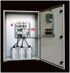
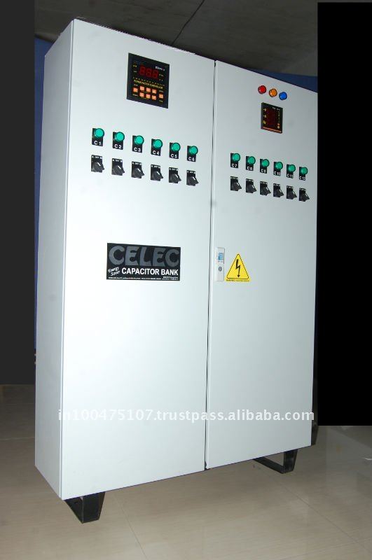
                    Here are some examples of tiny capacitor banks in comparison.


                    Programmable Wave Generator

                    The Programmable Wave Generator is a micro-processor based digital to analogue converter capable of storing arbitrary digital values in each of 72 registers, and then downloading them in sequence in order to construct electrical signals with 5 degrees of resolution. These signals are the intensified by means of a 1000 watt four quadrant amplifier. The resulting waves are then launched into various circuits and their effects upon impedance structures are studied.
                    Electrical Power is nothing more than a geometric arrangement of electromagnetic waves. Understanding the true nature of impedances and their interaction with electrical waves opens the portal to new dimensions of expression and control with respect to the geometry of electrical power.


                    Solid State Power Oscillator Circuit


                    Years of experimentation and thought on the subject of bi-directional, periodic, power flow have given rise to the foundations of an electronic circuit capable of effecting a true oscillation of power in an alternating current circuit. The ramifications of this kind of technology are staggering, for it promotes a return of unused electrical power to the grid system thus reducing the net consumption by the consumer and lowering his electric bill. However, this feat is achieved without any violation of natural law, and such circuitry will be relatively inexpensive to manufacture. The implementation of this kind of technology will constitute a win / win situation, for more power will be available to the utility companies without the burden of additional generation.


                    Engines Powered by Brown's Gas

                    The late Professor Yule Brown has been credited with the discovery of a new gas which bears his name. The substance is a chemical composition composed of Hydrogen and Oxygen which are bonded in a new way, thus forming a novel arrangement of the traditional water molecule. The resulting gas is flammable, and can produce temperatures in excess of 10,000 degrees Fahrenheit. However, the most remarkable property of this gas is its ability to implode when ignited in a confined space, and thereby produce an very high degree of vacuum.
                    During the late 1990's, myself and several colleagues, designed and constructed basic engines which could utilize Brown's as a fuel. The most exciting form of engine produced was a true atmospheric engine, which literally ran from the weight of the atmosphere itself. A Brown's gas implosion was used to produce a vacuum in a sealed cylinder, which was then vented to the atmosphere. The resulting pressure differential of 14.7 pounds per square inch was then utilized to produce useful work against a movable piston. This type of engine had enormous work capability, and produced only water vapor as exhaust.


                    Conclusion

                    Each of these technologies have staggering potential in the fields energy conversion and alternate energy supply. However, due to the current financial attitudes regarding investments in general, and high risk research and development investments in particular, it may take years for any of these discoveries to find application in the commercial world. It doesn't say much for our world when people with investment capital are more interested in fast food franchises then they are in the development of new technologies. Fortunately, this attitude is a fairly recent one, otherwise mankind would still be living in caves, hunting with spears and clothing themselves with animal hides.


                    Thanks Jim Murray
                    Last edited by BroMikey; 08-24-2014, 07:32 PM.

                    Comment


                    • #12
                      The geometry of the rotor of the dyna-flux alternator.

                      In this movie the experimenter angles a circular magnet but rotates it on opposite axis. a magnet inside a horizontal tube.
                      Is there a no lenz geometry ? one might place a few coils with load in sweeping motion field using green film, use a light weight motor.
                      watch if the speed decreases. Finding the no lenz setup along with the work in the previous post.
                      A good green film (amazon $4) should show simular sweeping on the solid state no moving parts serp.
                      This is why I am open to progressive design using epoxy iron because finding the shape is a step in the discovery.


                      https://www.youtube.com/watch?featur...gOi85CpM#t=309
                      Last edited by mikrovolt; 08-27-2014, 08:35 PM.

                      Comment


                      • #13
                        Originally posted by mikrovolt View Post
                        The geometry of the rotor of the dyna-flux alternator.

                        In this movie the experimenter angles a circular magnet but rotates it on opposite axis. a magnet inside a horizontal tube.
                        Is there a no lenz geometry ? one might place a few coils with load in sweeping motion field using green film, use a light weight motor.
                        watch if the speed decreases. Finding the no lenz setup along with the work in the previous post.
                        A good green film (amazon $4) should show simular sweeping on the solid state no moving parts serp.
                        This is why I am open to progressive design using epoxy iron because finding the shape is a step in the discovery.


                        https://www.youtube.com/watch?featur...gOi85CpM#t=309
                        Hi there

                        I think it more than just that. You see there are at least 4 poles and I think the angular rotating poles and the normal straight rotating poles are wired up so the expected results do not occur.

                        The poles are used so that an out of balance from the norm is accomplished.

                        It is not just a motor with an angular rotating set of 2 poles that is passing the coils. I am not sure what this experiment would show us.

                        Thanks for your entry.

                        Mike

                        Comment


                        • #14
                          Here is the truth.

                          These facts are clearly stated in the patent.

                          The rotor has 2 poles. The shape is an oblique 3d ellipse having two poles and no windings. it would need to be magnetic also distinguished from the rest of the rotor which is called non-magnetic

                          The stator has two input power windings and two output stator coils. The flux travels around the stator in one direction.

                          An experiment described would allow someone to start simple to observe the sweeping motion and understand how the stator works with the unique rotor.
                          The experiment is educational that furthers the new and useful benefit and is not an attempt get around paying royalty of patent.

                          Comment


                          • #15
                            I see it now

                            Originally posted by mikrovolt View Post
                            Here is the truth.

                            These facts are clearly stated in the patent.

                            The rotor has 2 poles. The shape is an oblique 3d ellipse having two poles and no windings. it would need to be magnetic also distinguished from the rest of the rotor which is called non-magnetic

                            The stator has two input power windings and two output stator coils. The flux travels around the stator in one direction.

                            An experiment described would allow someone to start simple to observe the sweeping motion and understand how the stator works with the unique rotor.
                            The experiment is educational that furthers the new and useful benefit and is not an attempt get around paying royalty of patent.
                            Yes Mikrovolt you are right I see that now.

                            I had mistaken the counter weights as poles but they are not poles.

                            So I see your point now. But the green film I don't get that.

                            Thanks for correcting my mess up.

                            Mike

                            Comment

                            Working...
                            X