Announcement

Collapse
No announcement yet.

Bemf Boost and Buck converters

Collapse
X
 
  • Filter
  • Time
  • Show
Clear All
new posts

  • Bemf Boost and Buck converters

    Buck Converters
    Boost Converters

    A possible circuit, not tested.
    Three or more chokes could be used with sequential and synchronous switching.
    The load is mostly fed with bemf.
    Half of the Answer is knowing the right Question

  • #2
    There's an animation about half way down the page that shows current flow expansion and collapse of the magnetic field that is really helpful for us rookies
    Half of the Answer is knowing the right Question

    Comment


    • #3
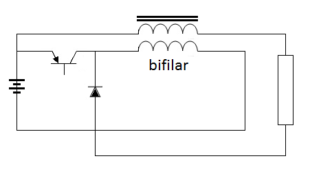
      Yet another untested circuit
      I'll get around to testing them, then I'll edit the post.


      Edit: This circuit works ok used a bifilar winding on a flyback core with a feedback winding to run the transistor.
      Powered up a 1w led using a AA battery that had less than 1v charge, very bright.
      I may scale this up in time.
      Last edited by Dave45; 10-29-2014, 10:57 PM.
      Half of the Answer is knowing the right Question

      Comment


      • #4
        I noticed I could run the load on either side of the bifilar.
        Next test Im going to push and pull on the load.
        Half of the Answer is knowing the right Question

        Comment


        • #5
          hi dave.this is the most efficient setup i have tried so far.credit goes to mr Qantstuff for diagram A.the diode between the - rail and vr1 has a forward voltage drop around .65v( i use a fr302 and a schottky 1n5189 in series).this keeps Q1 around the conduction threshold regardless of input voltage and vr1 adjustment which controls the base current.this approach provides crude regulation and makes for hard and fast switching and higher operating frequencies than usual.
          next trick is both windings and the battery supply power to the led.the red arrows show the path of emf when the field collapses.
          diagram B is modified to run off small solar cells pillaged from garden lights.the output charges 4 aa nimh cells in series.here only 1 winding and c1 push on field collapse but i got more efficiency this way because d2 is another 1n5189 with less v drop(.2-.3v), than going through d1.
          input is around 1.5v when the sun is out and output is up to about 5.4v so i added another winding for diagram C.this helps a little bit. 1.5 v 50ma in=5.3v 11.5ma out.that's over 80% which is decent for a simple diy converter,and that's with 2.2 ohm meter shunts and vr1 tuned aggressively,622 ohms,for max output current.with these circuits i have measured efficiencies around 85-86% with vr1 backed off but as it's solar powered why not go for max charging current.
          next step is to try diagram B with the third winding,L3 piggybacked on to L2.i need more solar cells to get say 80-100 ma at 1.5 to 2 volts.this will increase the charging current to the battery pack.
          solar panels have a different voltage/current curve to other power sources.for best performance they need to be matched to the load with the right series/parallel combinations.
          t1 is a mje340,hfe measures 75. c1 is 25v 4700uf,presumably low esr from a SMPS. inductor is a small ferrite torroid with 16 turns each winding.
          Attached Files
          Last edited by voltan; 10-31-2014, 12:47 PM. Reason: grammar

          Comment


          • #6
            Hi Voltan
            Cool, I will study your circuits

            I found I could run the base of my transistor from the end of my bifilar winding but not to start, to start I have to use the feedback winding then I can disconnet it.

            Interesting circuits, and fun to play with, I need to order some panel meters in the milliamp range to get better measurements.
            Half of the Answer is knowing the right Question

            Comment


            • #7
              bemf aided
              Havent tested it just playing with the schematic
              Half of the Answer is knowing the right Question

              Comment


              • #8
                Neither of these will work.

                Last edited by Dave45; 11-05-2014, 02:00 PM.
                Half of the Answer is knowing the right Question

                Comment


                • #9

                  Half of the Answer is knowing the right Question

                  Comment


                  • #10
                    Buck Boost mode
                    Half of the Answer is knowing the right Question

                    Comment


                    • #11
                      Half of the Answer is knowing the right Question

                      Comment


                      • #12
                        Dave when are you going to test these? Alot can happen in the realm of imagination. Proof makes something work.

                        Sorry

                        Matt

                        Comment


                        • #13
                          Iv tested the simpler ones
                          I have to think it out, set up a plan.
                          I'll build it soon
                          Half of the Answer is knowing the right Question

                          Comment


                          • #14
                            I know Iv posted alot of schematics lately, I had an idea and had to run with it, this page is like a notebook.
                            Iv learned alot studying buck and boost converters I not only study but I build and test too.
                            Something important I have learned, current is a product of electron flow


                            Watch the buck converter simulation Buck Converters
                            When the transistor turns off the current takes a path through the diode, if current actually came from the pos of the battery when the switch turned off the current would continue to feed into the battery until it was exhausted.
                            But it doesnt it goes through the diode this bugged me for awhile until I put it in the perspective of electron flow.
                            We have to build our circuits to accommodate both.

                            Im sure you folks that have been at this for a long time already knew this but it was a revelation for me.
                            I continue to learn study and test.

                            All the Best,
                            dave
                            Half of the Answer is knowing the right Question

                            Comment


                            • #15
                              If we look at the first schematic in this pic the one thats voided, according to conventional current flow it should work when the switch is on the current moves from pos through the coil to neg when the switch is off the current moves through the diode and cycles through the coils,,, but it will blow the transistor and here's why.
                              There is no alternate route for the electron, when the switch is on electrons move from neg to pos when the switch turns off there is no alternate route for the electron and the transistor is blown.

                              The second schematic allows for both electron and current flow
                              When the switch is on electrons flow from the neg to the pos and as a product of electron flow current flows from pos to neg when the switch turns off the electrons move through the diode and current enters the alternate path and both cycle through the windings.
                              I say both but actually its just the electron the current is a product of electron flow but both have to be accommodated when designing circuits.
                              Last edited by Dave45; 11-07-2014, 12:05 AM.
                              Half of the Answer is knowing the right Question

                              Comment

                              Working...
                              X