Announcement

Collapse
No announcement yet.

BiTT OverUnity Transformer Bi-Toroid Thane H. Bill A.

Collapse
X
 
  • Filter
  • Time
  • Show
Clear All
new posts

  • [QUOTE=Doogy2Shoes;270015]if it is any help, this 2009 thread discusses the device here (with some good video links included):

    Google Translate

    and here
    A truly overunity Transformer / Meg

    Here is Valeri Inavov's statement on this , rough translation:
    QUOTE
    In fact, my initial work had nothing to do with an electrical generator. Generator of electricity occur as a side, even accidentally. So now called me "work coil" was placed to be able to measure through its inductance, the rate of switching of the magnetic flux from the permanent magnet. Nothing more! At one point it appeared that this thing becomes a generator!
    The switch of magnetic flux from the permanent magnet INKOMP in itself is not a generator, as many think. He is a switch and nothing more. To become a member of the generator when it is sufficiently effective, it is necessary to do many more things. The main task is to create a sufficiently powerful magnetic field, and this magnetic field from a permanent magnet. Using a large number of these switches allows a relatively small volume to create a very powerful magnetic flux, and with very low energy consumption compared with the electromagnet. However, let's not forget that we manage a "free" magnetic flux - that of the magnetic field of the permanent magnet!

    Comment


    • here is an American patent application for an energy generator based partially on Ivanonov's work:

      ENERGY GENERATION APPARATUS AND METHODS BASED UPON MAGNETIC FLUX SWITCHING - Patent application

      Comment


      • Flux Redirector

        Originally posted by Doogy2Shoes View Post
        here is an American patent application for an energy generator based partially on Ivanonov's work:

        ENERGY GENERATION APPARATUS AND METHODS BASED UPON MAGNETIC FLUX SWITCHING - Patent application
        The figure 3 and figure 5 devices make sense, but the figure 7 one does not--this one the flux takes alternating paths, but still connects to the output coil in the same direction, North is always from one side; South always from the other. I don't think it was actually tested because clearly it wouldn't work the same as the other devices.


        If you made this device, attempted to distribute it and was promptly brought up on charges of patent infringement, maybe you could counter sue Ted Annis and J. Patrick Eberly for a fraudulent patent submission of a non-working device.
        Last edited by Dog-One; 01-15-2015, 10:30 PM. Reason: Added content

        Comment


        • Nice One-Dog

          I just happened to have two 6.6" toroidal core from micro-metals that are good to 500khz or better. But if it doesn't work, like you say, maybe it ain't worth our time.

          It will work. It is just like all these BiTT designs.

          Nice find Dog, you really got it on the ball. I don't know how you do it. These patents are just another validation to the fact that this BiTT work has been a known phenomena for quite a few decades.

          Patent US20090096219 - Energy generation apparatus and methods based upon magnetic flux switching - Google Patents

          Mikey


          Originally posted by Dog-One View Post
          The figure 3 and figure 5 devices make sense, but the figure 7 one does not--this one the flux takes alternating paths, but still connects to the output coil in the same direction, North is always from one side; South always from the other. I don't think it was actually tested because clearly it wouldn't work the same as the other devices.


          If you made this device, attempted to distribute it and was promptly brought up on charges of patent infringement, maybe you could counter sue Ted Annis and J. Patrick Eberly for a fraudulent patent submission of a non-working device.
          Last edited by BroMikey; 01-16-2015, 02:33 AM.

          Comment


          • Electricity generating apparatus utilizing a single magnetic flux path
            US 20070242406 A1


            https://www.google.com/patents/US200...ed=0CDQQ6AEwAw


            Comment


            • Studying...

              Originally posted by BroMikey View Post
              Nice find Dog, you really got it on the ball. I don't know how you do it.
              I've been studying these pages all week:
              https://en.wikipedia.org/wiki/Transformer
              https://en.wikipedia.org/wiki/Lenz%27s_law
              https://en.wikipedia.org/wiki/Magnetomotive_force
              https://en.wikipedia.org/wiki/Magnetic_reluctance
              https://en.wikipedia.org/wiki/Electrical_impedance

              And this video:
              https://www.youtube.com/watch?v=FUUMCT7FjaI

              What I cannot find is one single sentence that explains why the opposing Lenz flux pushes the amperage back in phase with the voltage. Why is this one thing so impossibly difficult to figure out?

              Sure we know it does it, but why, or better yet, how?

              I'm starting to think nobody really knows. A good explanation can't be that difficult to come up with. If we had it, we could build exactly what we want and actually understand its operation.

              The search continues...

              Comment


              • kirchhoff law

                Originally posted by Dog-One View Post
                And this video:
                https://www.youtube.com/watch?v=FUUMCT7FjaI

                The search continues...
                Kirchhoff law is for the birds he says. +0.9v and +0.1 = 1 volt according to Faraday. Kirchhoff law states the answer to be 0 volts.

                Thus Kirchhoff law is for the Birds he says.

                Good video Dog you been holding out

                Mikey

                Comment


                • Maybe a little

                  Originally posted by BroMikey View Post
                  you been holding out
                  Nothing great to report yet, but hopefully I haven't been wasting my time.
                  Attached Files
                  Last edited by Dog-One; 01-17-2015, 07:31 AM.

                  Comment


                  • Originally posted by Dog-One View Post
                    Nothing great to report yet, but hopefully I haven't been wasting my time.
                    Ding Dong tubular bells. You rascal I knew you had sump-in up yer sleeve

                    Humm... That there looks like a fast freddy design with a whole lot-a-ringin goin on. Am I striking a note?

                    Copper tubular bells is what I call it. Is there a tube pattern? Or are these tubes random? I remembered Fast Freddy had one big tube in the middle and some smaller ones all around, but it looks like he turned out to be a liar/robber.

                    Still geometry has it's place in the cosmos. I see you name it LLT?

                    When you get a chance run it's operation by us. Especially ME

                    Mikey out

                    Comment


                    • Originally posted by BroMikey View Post
                      What's the connection between FREE Energy, Antigravity and Superconductivity?
                      By William S. Alek
                      President and CEO
                      March 16, 2014

                      Knowing this answer is the KEY! A KEY to liberating humanity from artificial scarcity brought about by The Matrix, the system in which we ALL live.


                      What Causes Superconductivity?

                      A key observation in this article about Superconductivity is the following "... the crucial realization is that superconductivity is associated with a bound pair of electrons, each having equal but opposite spin and angular momentum, traveling through the metal ..." This is also known as "Cooper Pairing."

                      http://qudev.ethz.ch/content/courses..._of_SC_6_7.pdf

                      The key is opposite spin and angular momentum! Because of opposite spin and angular momentum, the spin and angular momentum of the pair CANCEL. The pair loses it's inertia and effectively DECOUPLEs from the inertial field - the pair moves in the metal with NO resistance. In other words, the metal has NO electrical resistance and becomes an "ideal conductor" of electricity.

                      An almost identical effect occurs in the SFT or Split-Flux Transformer with one important difference. The SFT becomes a Superconductor at ROOM TEMPERATURE! This is how its done: You'll observe in the diagram above that electrons with opposite spin and angular momentum form "Cooper Pairs" due to lattice forces of the metal. The phenomena can only occur when the metal is conducting current at very cold temperatures (i.e., when cooled with liquid nitrogen). Above that critical temperature, phonon interaction breaks up the pairing of the electrons. Each electron now has spin and angular momentum. Thus, connecting each individual electron to the inertial field giving the metal electrical resistance.

                      In the SFT or Split-Flux Transformer, a similar action occurs. Because there are two output coils wired in a bifilar configuration, identical output current flows, but in opposite direction. An opposing magnetomotive force is created causing "Cooper Pairs" to form as shown above. This phenomenon occurs below, at or above room-temperature. The SFT effectively becomes a Superconductor at any temperature! How do we know this phenomena is occurring? Because the primary input coil becomes an "Ideal Inductor." In other words, the phase angle between the voltage and current approaches 90 degrees. I can easily demonstrate this phenomena. NO practical transformer on Earth can do this except the SFT!!! What this means is the SFT driving a REAL load consumes NO REAL power, or Pin -> 0 Watts! The ultimate overall efficiency of the SFT is nearly infinite!


                      So, imagine that - nearly Infinite efficiency! This is critical for understanding gravity and how this device interacts with gravity due to the inertialess reaction of "Cooper Pairs." Counter-rotating opposing magnetic fields is the KEY towards building antigravity technologies. The craft is essentially transformed into a macroscopic "Cooper Pair," DECOUPLED from the inertial field. FREE Energy is a byproduct of the process.

                      In my opinion, this is perhaps the GREATEST invention of the century, perhaps ever! Because it can transform and replace The Matrix.

                      Hi BroMikey
                      I have tried to calculate the same calculations with a pocketcalculator but i don't come to the same results.Also by Bill Alek's Video i have pressed the same button's(calculation is not my strenght ).Can you explain me how they calculate?Thanks

                      Comment


                      • Old Math Posts Forelle

                        http://www.energeticforum.com/renewa...-heins-19.html


                        Originally posted by BroMikey View Post
                        Thanks Again Dave

                        Thats a lot of winding coils this one that one and nothing, AAA?

                        Well i am getting a 75 degree shift on this BiTT over here. It is anything but normal. A normal transformer shows a shift of a few degrees and thats all you are ever going to get out of it.

                        The way it looked over here at first before I add the cos value was 3X current going in. Then when I figured the 75 degree shift things change.

                        For instance without and caps for tuning I got 8.2vac X .3amps = 2.46 watts going in. That is what it looks like if you don't use the COS. In my case with the BiTT the COS of 75 degrees is .26 but with a normal transformer the COS of 15 degrees is .97 that is a huge difference.

                        My 2.46 watts X .26 = .64 watts is real only the large portion keep circulating.

                        On the other hand a 2.46 watt X .97 = 2.39 watts real power used up out of 2.46 watts. This is a standard reading for a conventional transformer.

                        My output with no tuning is 4.5vac X .120 = .54 watts real used up without even trying that is 85 percent efficient. I have no tuning, poor coupling, not high frequency and still right off the bat I am 85 percent.

                        Totally incredible. Just generalizing from previous figures with poor coupling no frequency just tuning I see over 100 percent.

                        The previous numbers were all good except the amp reading on the input was 3X higher than I thought then I turned right around and cut that value into quarters so my figures were good as far as I can tell. Just arrived at wrong.


                        I will redo all of the figures. a 75 degree shift is .26 meaning if I input 1 watt I am only using approx 1/4 of that so .26 or 26 percent is used, the rest it sent back for recycling.

                        For every watt your standard transformer runs on uses up 96 percent of that.

                        So my BiTT needs work sure but will one day give me a 1:4 ratio something a conventional transformer can never do with this experiment.

                        Wow Wee is all I can say.

                        See before I was thinking 85ma was on the input when it was more like 300ma. So before I was saying 9.6vac X .085 = .815 watts

                        instead it should read 9.6vac X .300 = 2.88 watts but now I use the .26 COS calculation that I never used before so this is less on the input than I thought. The input would be 2.88 X .26 = .75 watts when before I thought of the input as .815.

                        So you see I am getting 125 percent after all.

                        I will make sure, don't get me wrong I am pretty sure like before but this time maybe I won't be as far off with the calculations.

                        Mikey

                        Comment


                        • Forelle Answer

                          This is how the math is done


                          Originally posted by BroMikey View Post

                          The most important thing BILL A pointed out was that conventional transformers use up or burn up approx 100 percent of what they run on.

                          Not so with a BiTT as you well know. BILL did show a 90 degree shift with the secondaries shorted out with a 1 ohm resistor.

                          Are you saying if I run without a load, I should get 90 degrees? Well its a new field and I didn't think of that yet. Maybe I better hear more.

                          Any other tests you have in mind? Let me know.

                          I am speaking in general terms using the same calculations and load resistance, being a set a 5 small lights that won't take more than 120ma no matter how much power you put to them. The voltage climbs after the amps stop rising.

                          You see for days I had been making calculations using wrong methods, no one inquired or asked. Everyone just assumes everything or don't have time, to busy whatever I am learning by watching the Thane videos, the Bill A video, the Mr clean Video's.

                          I am a green horn, can't run a scope worth beans, never run a reactive COS calculation til today. I have no idea what is in other peoples minds unless they talk and I sure don't know what I am doing.

                          Thane does, Bill does, and now so do I.

                          A special thanks to those guys.

                          BILL A had a figure of 78 degrees so 15.75 watts was measured X .20 = 3.2watts I think is all it used out of the 15+ watts.

                          You see I was just using raw numbers and you experienced guys didn't bother to check me out to see if I was doing it right

                          You guys should know better than that I'm gonna catch up soon.

                          Mikey You are Right DOG here in this video
                          httphttps://www.youtube.com/watch?v=QHZAzlqEKns://

                          Originally posted by BroMikey View Post
                          I have some new figures 128 percent all the way down to 60 percent
                          Check this page in 5 minutes again and I will have finished the calcs


                          Okay here are the low down DOG figures.

                          I had originally made a mess of my old calculations yet it seems they were actually right on arrived at wrong. Let's talk about that later but reactive power in caps can give real power figures.

                          Here we go, and this time I used 70 degrees COS figuring instead of 75.

                          Before tuning with caps

                          Input 189ma X 6.64v = 1.26 X.34= .43 watts real

                          Output 89ma X 3.29v = .30 watts real COP 69percent

                          next set of calculations

                          Input 153ma X 4.95v = .76 X.34= .26 watts real

                          Output 76ma X 1.82v = .14 watts real COP 54percent

                          one more set then I will be back in 5 minutes

                          Input 245ma X 9.38v = 2.30 X.34= .78 watts real

                          Output 110ma X 5.42v = .60 watts real COP 77percent

                          So this is very low. Next I will show figures with caps

                          wow wee did I flip out when I hooked up my same caps I used last week. I tuned it last week and the light jumps way up for less power input by far with only a 2-3 degree change in phase angle.

                          This calc is for a single cap on the input and one on the output.

                          Input 270ma X 9.50v = 2.56 X.34= .87watts watts real

                          Output 130ma X 7.60v = .988 watts real COP 114percent

                          Now I added one more big cap on the input dropped even more with a 2 degree shift. It doesn't work better loading this BiTT to 45 degrees.

                          We must stay at the 70-90 degree range.


                          the best ones


                          Now I am using 50uf on the input and 35uF on the output with a phase angle around 72-75 so lets say 70 degrees COS is .34 same as before just rephrasing for those who are beginners like "yours truly"

                          Input 245ma X 9.62v = 2.36 X.34= .80 watts real

                          Output 131ma X 7.70v = 1.01 watts real COP 126percent

                          Last calc for today


                          Input 200ma X 8.28v = 1.656 X.34= .56 watts real

                          Output 117ma X 6.15v = .72 watts real COP 128percent

                          So we can see this is a very low OU system that must be improved upon.

                          Tuning means a lot to brightening up the output lights and man what a difference.

                          Mike

                          Comment


                          • Circuits

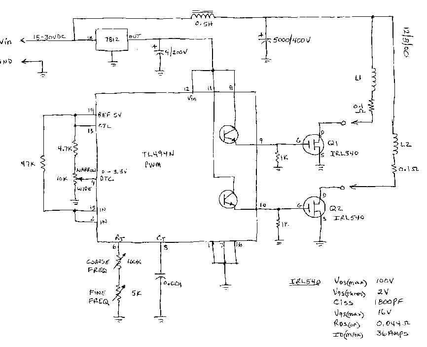
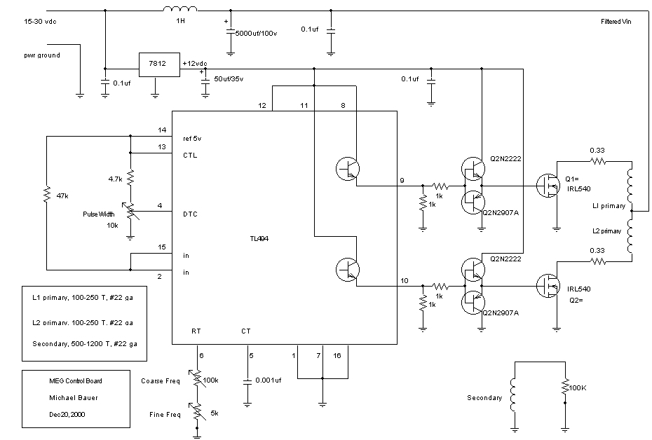
                            Diagram TL494


                            Originally posted by BroMikey View Post
                            MEG driver


                            Comment


                            • Auroratek 2015 is here

                              Jan 2015 BiTT conference.


                              https://www.youtube.com/watch?v=nQyx-V0d_nw


                              Comment


                              • Hi BroMikey
                                When i type in my calculator 10.75 x 1.466 x cos 78 i get -13.5185
                                when i type the same in my PC calculator i get 1229,241.
                                When i type in my smartphone i get 1229,241.
                                How is it done that 10.75 x 1.466 x cos 78 =3.277
                                Thanks

                                Comment

                                Working...
                                X