Announcement

Collapse
No announcement yet.

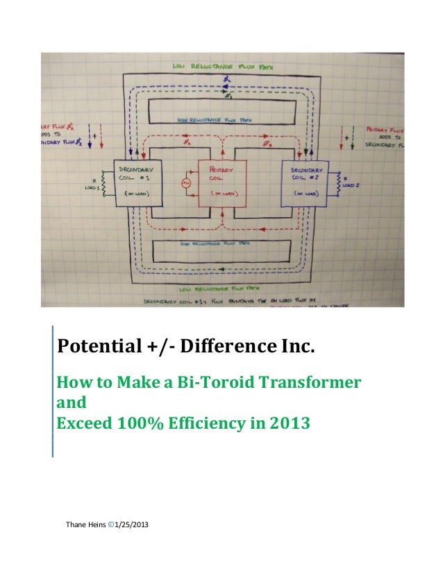
BiTT OverUnity Transformer Bi-Toroid Thane H. Bill A.

Collapse
X
 
  • Filter
  • Time
  • Show
Clear All
new posts

  • Hi folks, Hi mike, going to try a small bitt using these ferrite flyback cores i just pulled out of the coil forms.
    The bottom core pieces are larger than the top primary pole piece.
    This should help keep the induced secondary magnetic fields within the bottom core and reveal some effects, we hope.
    peace love light

    Comment


    • Hi folks, making progress on my small bitt transformer setup.
      Don't mind the hot glue, i used that for the coil formers.
      Each secondary is using many turns of 30awg. magnet wire.
      I will try and get each secondary close to same ohms, even if that means removing some windings from one coil.
      Will be winding the bifilar primary next, using 24awg. magnet wire.
      By using bifilar, i can test with joule thief type oscillator or simple flip flop type circuit.
      peace love light

      Comment


      • A very go direction to go in if you ask me. Evidently the Tesla
        statement "Phase Conjugate mirror" can be setup in many ways.

        Marc shows us his PELEX box the size of a 3x5 card, calling the
        contents "BUCKING COILS" then Bill Alek did the same thing as Thane
        with a Bitoroidal.

        Marc uses a shallow ground of a few inches deep with the remainder
        of his copper pipe (10") sticking straight up gives him and extra 1500
        watts when he pumps 1000 watts.

        Boyce uses a toroidal with 3 bucking coils in a rotational pattern to
        produce his "PHASE CONJUGATE MIRRORING" effect.

        Thane does his REGENX effect with high impedance coils where energy is
        stored in the coil at no great losses then returns the energy to the rotor
        a sort of reflected energy or mirrored energy.

        Originally posted by Ajay View Post
        In one of Tesla's lectures, he describes the construction of a induction coil which is a bucking coil design. He said that the "electromagnetic fields cancel" in the space between the coils. He also said that the "electrostatic" effects at the open end were "sufficient" to replicate most of the interesting high frequency phenomenon he describes in his lectures. I am building a replication of it and running it with an LMD Analog computer, I will post my results in this thread.
        Bucking coils certainly exhibit strange properties when they are put under load, though.
        At resonance, properly constructed bucking coils are OU.
        Bedini's Kromrey Converter uses them as well.
        Last edited by BroMikey; 12-02-2015, 11:01 AM.

        Comment


        • Hi mike, we shall see what results i can muster with this setup.
          It is built, now just have to build a pulse circuit, i will start with a simple blocking oscillator circuit.
          peace love light

          Comment


          • Hi folks, Hi mike, i started making some tests on this setup.
            I started with a simple flip flop circuit, for squarish wave AC.
            I started out at a lower frequency at 12 volt input.
            The no load amps were around 200 milliamps.
            With 10 ohm, 10 watt resistor on each secondary, the amps increased to 260 milliamps.
            I Then placed another set of ferrite c-cores of similar size underneath, though they are at least 1/2" away from other main ferrite secondary cores because of hot glue, though the input did reduce by 10 milliamps or so.
            It's possible i need to rebuild this with double the size ferrite secondary cores.
            I then increased the frequency of the oscillator, by upping the resistors to 10kohm from 1kohm.
            This caused the circuit to draw 30 milliamps no load and slightly reduce when under load.
            Interesting so far, will be making further tests with this setup, using flip flop and blocking oscillator, then will probably rebuild it.
            I tried powering a 6 watt led bulb off each secondary, though only one will light if the 10 ohm resistor is connected to one secondary and led bulb to the other.
            peace love light
            Should also point out, i have not balanced the secondary coils ohms value.
            Last edited by SkyWatcher; 12-05-2015, 07:03 AM.

            Comment


            • Been watching you talk. Try connecting the secondaries different ways.

              In series, bucking and in parallel. Tuning each coil with small value caps

              high voltage disk shapes.

              Your primary is very large for a 10volt PWM input. Generally the larger

              primaries are associated with 60hz operation. Bill Alek uses smaller

              primaries when using pulsed energy.

              With your current system I recommend you run off a variac at 10volts

              60hz for a first test. Do you have a working variac?

              How many ohms for the primary?

              Comment


              • Hi mike, thanks for tips, been trying all the different coil wiring configurations, no capacitors yet.
                I've found in series gives the best output to a 470 ohm load, however the current rises from 100 milliamps no-load to 130 milliamps loaded to around 1/2 watt output.
                Each bifilar primary strand is 1.4 ohms.
                One secondary is 14.3 ohms, the other secondary is 13.7 ohms.
                So i need to remove some of the 30awg. windings from one of the secondary coils.
                I will mention input outputs when things look more interesting.
                I don't have a variac.
                One thing of interest though, i just made a test of each secondary coil, individually shorted and the input drops below no-load to 90 milliamps.
                So maybe the imbalanced secondary coils is causing the loaded increase in current.
                I will now balance the secondary coils and then make some more tests.
                This is the circuit in use at the moment, though with 2n3055 and different resistor values, 5 kohm at the moment.
                peace love light


                Edit: ok so i matched the secondaries, both are 13.5 ohms, did not seem to change anything much as far as loaded amp draw increase, meaning it's still increasing under load.
                Last edited by SkyWatcher; 12-06-2015, 03:07 AM.

                Comment


                • I guess you lost me on how your complete circuit diagram
                  looks. Your last picture was a pulsing transformer I think.

                  Do you have a complete diagram? Or is this a complete diagram?
                  I don't know for sure. I seems you are using a 120v-14v stepdown
                  transformer to make pulses and then you send that to the BiTT.

                  This is a typical BiTT wind job. One primary and two secondaries.

                  Last edited by BroMikey; 12-06-2015, 03:55 AM.

                  Comment


                  • Originally posted by SkyWatcher View Post

                    Edit: ok so i matched the secondaries, both are 13.5 ohms, did not seem to change anything much as far as loaded amp draw increase, meaning it's still increasing under load.
                    What's still increasing under load? The primary? Or the Secondary? or the
                    wall adapter pulse transformer?

                    You mean as you load the secondaries the primary increase also?

                    If it is the later I think it is because you need a huge amount of windings
                    on the secondaries. I think I figured I would need 3- 5 times as much
                    copper winding on a ferite core as an iron core uses.

                    The best way to gain this perception is to look at Thanes 60hz model.

                    If you have decided to follow Bill Alek by using low voltage pulses and
                    less copper that is another story altogether. It looks like you have come
                    up with a new design?

                    It is probably not a good idea to design one first, rather build one
                    by following a successful design. If you use the Bill Alek idea remember
                    he used an adjustable audio amplifier to around 3000 hz to tune
                    his coil windings.

                    If Thanes idea is being used you will tune by raising and lowering
                    the voltage because the freq. is a constant 60 cycles.

                    YOU MUST TUNE.
                    Last edited by BroMikey; 12-06-2015, 04:10 AM.

                    Comment


                    • Tuning

                      Anyone attempting to build a BiTT and is winding up a random
                      set of coils thinking they have it will meet a wall. Random windings
                      must be tuned either by adjusting voltage or freq.

                      We are wandering around in the dark as to which exact winding
                      will allow us to operate at any given voltage. Once the awg wire and
                      length is found to match a voltage the freq will also be important.

                      If you are using frequencies. In the pulsed version 3000hz is far
                      from the concept model Thane runs at 60hz.

                      Popping a coil upon to the table and plugging it in is only
                      the start of a very long process of making more coils and
                      changing the voltages to search for the best results.

                      In Thanes 60hz models the primary core material is not the
                      same as the secondaries run on.

                      The trick is to run the primary up to saturation but not
                      saturate. On the edge. Then the secondary arrangement
                      is made to reduce the resistance as compared to the primary
                      portion of the BiTT.

                      At this point you will see good results and not before.

                      Even Thane only got an output of 60volts with all of that
                      winding because it just turned out that way. Tuning by
                      adjusting the voltages to the load to keep the primary
                      on the edge of saturation.

                      He must of had 25 pounds of transformer there.
                      Last edited by BroMikey; 12-06-2015, 04:27 AM.

                      Comment


                      • Hi mike, no it only has a bifilar coil in place of primary, this way i can use it for this circuit and a blocking oscillator more easily.
                        No transformer is used, just a 12 volt battery for input, sorry for the confusion.
                        The primary is increasing under secondary loading when secondaries are in series.
                        Unfortunately my memory is a bit cloudy of my previous research of thanes stuff, am trying to refresh me memory by researching again.
                        Though maybe i should look at bill's work more.
                        I will try some different test with this flip flop circuit some more, maybe use a laptop psu and pump 20 volts in to get the frequency up and a little more power through.
                        At least something different is happening, secondary short circuit lowers primary input amps.
                        peace love light

                        Comment


                        • When I started my BiTT I was aware of the differences between
                          the high and low voltage or frequency BiTT designs so this is what
                          I decided. Since Thane was using atleast 3X more windings I should
                          use a conventional winding format running it at 5-10X lower
                          voltages.

                          This gave me the same proportions. So I used 180 turns of awg
                          24 on all three windings on ferite core. This arrangement will
                          start getting warm wires on 60hz@30v.

                          So i run all of the way up to 25v and no more. As i spent many
                          hours adjusting my variac and changing loads or wiring patterns
                          the best was found for those identical coils.

                          Also I watched the phase angle on the scope.

                          Comment


                          • Originally posted by SkyWatcher View Post
                            At least something different is happening, secondary short circuit lowers primary input amps.
                            peace love light
                            yes and so you should be running a resistive . A 2v flashlight.
                            Like a small light bulb offers. This will give you lower voltage
                            outputs but better phase angle.

                            We need a 75-90 degree phase angle. Shoot for that.


                            [VIDEO]https://www.youtube.com/watch?v=x7JDElxCyX4[/VIDEO]

                            [VIDEO]https://www.youtube.com/watch?v=Ivm8aaQu00w[/VIDEO]
                            Last edited by BroMikey; 12-06-2015, 05:31 AM.

                            Comment


                            • Hi folks, Hi mike, well i've been making many more tests and am now testing with a blocking oscillator.
                              I had a thought to try and it was a positive result, though it may work just as well with the modified ac wave pulser (flip flop).
                              I instead only placed one of the primary core legs on one side of the secondary core and the input current stay the same or slightly dropped when each secondary coil was loaded.
                              However, if one of the secondary coils is not loaded, there is no voltage across the other secondary resistor load.
                              Input current also drops slightly when secondary coils in series across resistor load.
                              This result may just mean that my secondary core needs to be bigger or a lower reluctance, which may then work with both primary core legs placed in proper position.
                              Thoughts welcome.
                              peace love light

                              Comment


                              • Anyone can make a Bi-Toroidal Transformer BiTT at almost
                                any coil size with good core material and at one voltage the
                                double secondaries will always out perform a standard transformer.

                                And like you say for any target voltage you may want to change the
                                coil properties but look at it like this again.

                                My 3" Diameter coils have 180 turns on them figure circumference
                                2*pie*r = 6.28*1.5'=9.42" per turn = 9.42" X 180 turns= 1695 feet.

                                Now that is a mess of wire. But then I am only at 60hz.

                                But either way all coils can be tuned to get the extra. Any coil.

                                Keep up the good work.
                                Last edited by BroMikey; 12-09-2015, 09:25 AM.

                                Comment

                                Working...
                                X