Announcement

Collapse
No announcement yet.

Topic: The new generator no effect counter B. EMF part 2 ( Selfrunning )

Collapse
X
 
  • Filter
  • Time
  • Show
Clear All
new posts

  • Cadman

    Your cad work is is much appreciated as when actual building progresses, things like this reduces errors and cost. Is it possible to test out UFO's drawing above? It would be helpful to see if that changes anything. Another idea is if you can, to reshape the Iron with the tapered out ends as seen in the film. When I saw these ends and all the work that went into cutting them, it said to me that these were important geometry changes.

    Prochiro
    Last edited by prochiro; 12-30-2014, 05:42 PM. Reason: add another idea
    "Today's scientist have substituted mathematics for experiments and they wander off through equation after equation and eventually build a structure which has no relation to reality."
    Nikola Tesla

    Comment


    • Thanks Dragon. I hope it's a winner too!


      Prochiro,

      Thanks for saying so. When we share our efforts, we all benefit.

      As for testing Ufo's drawing I suppose I could apply that to my 4 pole setup but I am not sure it would work out the way Ufo intends, since so much depends on the flux circuits and configuration of the generator.

      Good catch about the tapered ends, they are important. My software can not layout complicated shapes (or I don't know how to do it) but there is no mystery about the ends. There is a very high concentration of flux at the edges of the rotors (or pole shoes) that will cause heating. If I recall correctly, it's due to eddy currents there and flaring out the ends reduces that concentration.... old info from the early days of dynamos.

      Related to that, and something I haven't seen mentioned, the outer face of the rotors should have a very slight taper towards those ends. This increases the air gap and reluctance towards the ends and spreads the flux more evenly over the outer rotor face. Look at one of the images I just posted, that taper isn't there and see how there are fewer lines above the rotor where the flux splits directions? The flux isn't as dense above the center of the rotor shoe and this will cause a ripple, or unwanted harmonics, in the induced emf. This is another tidbit of old knowledge I stumbled onto. I have a formula somewhere that calculates the taper depending on the width of rotor shoe. I'll post it later.

      Regards

      Comment


      • Posted at OUR Forum

        [quote author=T-1000 link=topic=2678.msg43941#msg43941 date=1419949203]
        Hi Luc,

        I wonder - is it magnetic attraction causing initial 83 watts to be used in your setup?
        If the drill motor is causing that I bet it is best time to exchange it to smaller pulse motor which will consume less than 10 watts if magnetic attraction is not so big..

        Also I have suspicion about geometry there - if the C core is passing magnet by approaching and leaving it directly on N/S poles vectors the magnetic force is largest.
        To see what I am about get two very strong magnets, snap them together and try to separate them apart. You will see how much force is required just to do that. And if you start sliding them on the side the force required to separate them is much smaller.

        Cheers!

        [/quote]

        Hi T-1000,

        I made 3 videos to demonstrate and answer your questions.

        First video is to explore magnetic cogging on the cores. As far as I'm concerned, the pull and push forces are equal so we should be breaking even when rotating the C core over the I cores less Eddy current losses in the cores.
        Video demo: https://www.youtube.com/watch?v=lDR0lfv4BgU

        Now lets explore the power needed just to turn the drill press and C core rotor.
        Video Demo: https://www.youtube.com/watch?v=tXkNJZ9K_Ks

        So with no I cores present we need 54 Watts
        and with I cores present we needs 87 Watts

        So we have 33 Watts needed to turn the C cores over the I cores.
        Here is a video demo where I load the coil
        https://www.youtube.com/watch?v=-LiYwiDrbMM

        So we can get 5.3 Watts out of the coil plus we need to consider the coils DC Resistance of 1.3 Ohms which may represent another 4 Watts. So we can get 9.3 watts out plus the coil under load assists the rotor and drops the prime mover power by 4 Watts.

        So we can account for 13.3 Watts! ... so where is the rest of the power going?
        There are other losses involve which we need to consider when using Iron or soft steel laminations. I think we may need to consider Iron Powder Cores! (keep in mind this is not hard like ferrite cores)
        TinMan has made a great video to demonstrate steel lamination losses
        https://www.youtube.com/watch?v=uAXtB_7RkEg

        Share your thoughts.

        Luc

        Comment


        • Wow great work cadman. Incredibly helpful thanks.

          Dragon thanks for the chart. Off to the scrap metal yard today
          Stew Art Media

          Comment


          • Originally posted by gotoluc View Post
            Posted at OUR Forum
            There are other losses involve which we need to consider when using Iron or soft steel laminations. I think we may need to consider Iron Powder Cores!

            Share your thoughts.

            Luc
            I think I suggested it earlier but you can use Soft Iron Buckshot and Iron Filled epoxy

            I know buck shot can run from 0 - 20 khz with a real low loss. I haven't tried the epoxy yet, I doubt it has enough iron to be productive but as far an epoxy mix goes it can't hurt.

            Matt

            Comment


            • Luc - may I pose some questions to consider... Is the core/magnet/coil producing an optimum use of flux through the coil for maximum output?

              Is there a different configuration that would allow optimum flux penetration through the coil?

              You have magnetic poles 90 degrees to the coil, cores are fully saturated and the only way to cause change is to decrease that field or short it as it were... how does the field act within the coil? Is it possible that only small portions of the coil is seeing any sort of change?

              Lets say you convert what you have to a conventional alternator - place 4 magnets on the bottom of the C's NNSS, remove the central magnet and replace it with a core. Would the output increase or remain the same? Would the coging remain the same or increase?

              You are an excellent builder, question everything and the answers will fall into place.

              Comment


              • Luc,

                The reason you get the highest output when each end of the c-core is between and connecting the legs of the i-core is because that is the point of least magnetic reluctance. The flux is not traveling across the whole c-core then, it is flowing between two legs of the i-core on each end and across the tip of the c-core. Just the ends of the c-core are conducting flux at that point. Like this |][| All 4 legs of the i-core are conducting flux then instead of just 2, so twice as much wire is induced.

                You might get a higher output if the c-core overlaps 50% of each i-core leg. But that would only be true if the current overlap is incapable of carrying the amount of flux you are using. Judging by your scope trace it looks like it's handling it just fine, but still might be worth a try.

                Regards
                Last edited by Cadman; 12-31-2014, 05:19 PM. Reason: Clarity.

                Comment


                • Hi everyone,

                  Happy New Year

                  here is a video update of what I've been working on for the past 2 days

                  Link to video: https://www.youtube.com/watch?v=jnTImIQlAms

                  Stay tuned for the test results

                  Luc

                  Comment


                  • Originally posted by dragon View Post
                    Luc - may I pose some questions to consider... Is the core/magnet/coil producing an optimum use of flux through the coil for maximum output?
                    Hi Dragon,

                    Happy New Year and sorry for the delay in reply.
                    I would say my test device is not delivering maximum output to my coil.

                    Originally posted by dragon View Post
                    Is there a different configuration that would allow optimum flux penetration through the coil?
                    I sure hope there's a better version then mine. Do you have a better working version you can share?

                    Originally posted by dragon View Post
                    You have magnetic poles 90 degrees to the coil, cores are fully saturated and the only way to cause change is to decrease that field or short it as it were... how does the field act within the coil? Is it possible that only small portions of the coil is seeing any sort of change?
                    I agree! the I cores don't have a large change the way it's setup.


                    Originally posted by dragon View Post
                    Lets say you convert what you have to a conventional alternator - place 4 magnets on the bottom of the C's NNSS, remove the central magnet and replace it with a core. Would the output increase or remain the same?
                    I would say the output would increase but would it not basically be a standard Generator at that point?

                    Originally posted by dragon View Post
                    Would the coging remain the same or increase?
                    Possibly half the cogging

                    Please show us how your device works

                    Luc

                    Comment


                    • Luc, nice build, can't wait to see your test results! You finished that one quick.

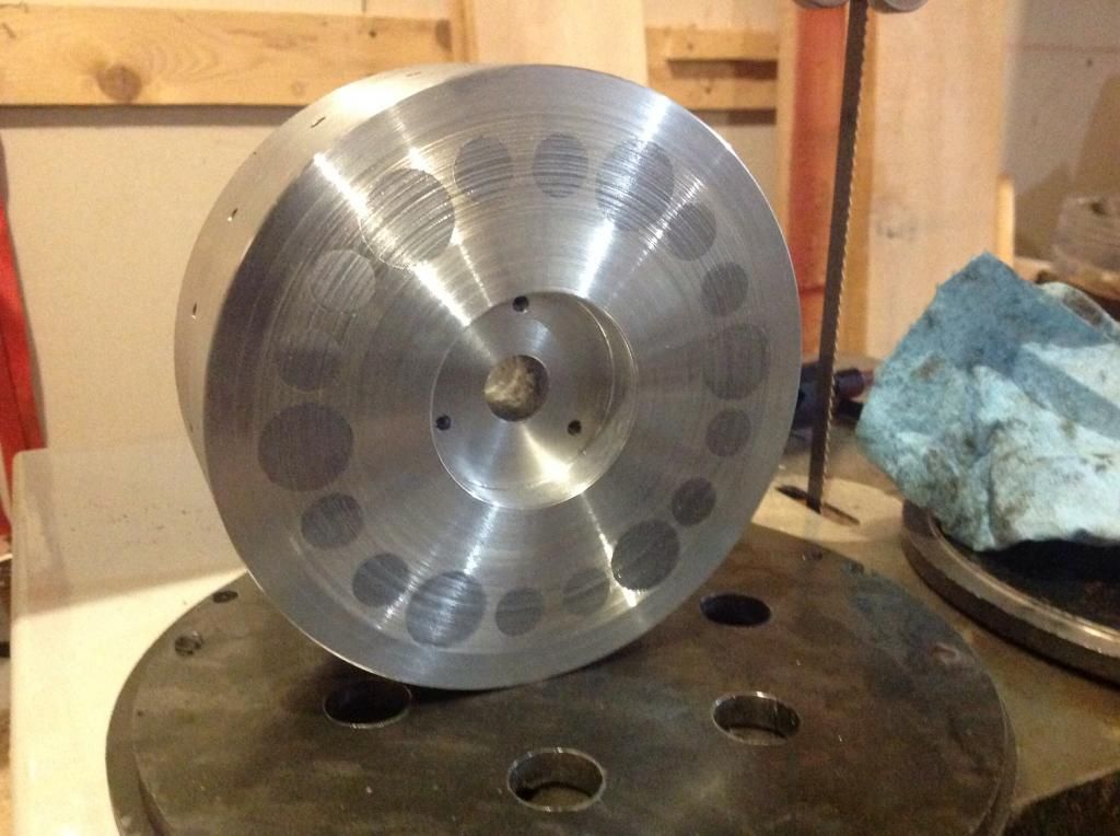
                      Well, I finished the rotor, and incredible cogging, so after UFO' s post I drilled out the rest of the rotor, now there are 18 directors, 6 @ 3/4, and 12 @ 1/2.
                      No overlap, but way less cogging.


                      No reason why one, couldn't fill an area with say 1/8 rods. Lots of work, but I'm sure it would even work better. I've only been spinning by hand.

                      Comment


                      • Originally posted by gotoluc View Post
                        Hi Dragon,

                        Happy New Year and sorry for the delay in reply.
                        I would say my test device is not delivering maximum output to my coil.


                        I sure hope there's a better version then mine. Do you have a better working version you can share?


                        I agree! the I cores don't have a large change the way it's setup.


                        I would say the output would increase but would it not basically be a standard Generator at that point?


                        Possibly half the cogging

                        Please show us how your device works

                        Luc
                        You guys have some awesome creativity and building skills ! I posted the questions to fuel thought not necessarily to get answers. These and hundreds more are what I've been asking myself as I progress.

                        The premise of my build(s) is based on the fact the alternator is a conventional alternator in how it functions - all the same rules and formula's apply - the only difference is how we are addressing the polarity change and re-directing Lenz forces.

                        My second build - the basic drawing I presented originally - may have been a bit confusing and as such not well understood. I redrew it to appear more like what Luc had built prior to his newest model, hopefully to clarify it a little... this is the direction I chose and shouldn't be considered the only way it could be accomplished. Below is the basic drawing...
                        Last edited by dragon; 01-16-2015, 12:49 PM.

                        Comment


                        • This is a small detail of my progression from the beginning and problems I found along the way...

                          The first one ( shown with the 2 large coils ) started with just 2 poles. This one was doomed to fail but it was a start. It produced excellent voltage but very little current because the cores couldn't relax or normalize enough between pulses to cause much change.

                          The second, which was initially the first modified, used 2 poles per side ( as in the drawing ) worked much better because of the forced change. Because of the axial design the forces caused problems with the rotor flexing and I really couldn't take it to it's limits so I needed a better design that helped balance out the magnetic forces and I couldn't measure the forces on the stator itself. I suspected that it was offsetting the Lenz forces but had no reasonable modification that could be easily adapted.

                          The third had to solve all the issues prior. The little 6 pole fan motor was handy so it became the donor to the next project. This one showed me that everything was as I suspected... Measuring the output with a scale on the stator showed there was little to no Lenz present when loaded. I suspect there is a bit of residual Lenz on the changing forces on the directors but it is very small. The main problems that presented themselves at this point was the coging forces - these required more power than the output. After calculating a conventional alternator and comparing it to the dimensions of what I had it would be a simple change to make it produce more... but instead I decided to go with something I had more room to work inside and I will return to this smaller build at a later date..

                          The Pincore 3kw became the next donor - although it looks "roomy" at first glance I realized I needed to pack a lot of parts in that small chamber... quite a challenge in itself. The first rotor consisted of 2 director poles and 6 magnets. Output was very low and checking the flux transfer with a gauss meter quickly showed why.

                          I'm still working on the next rotor assembly and early tests show I'll fall short of matching the OEM rotor but significantly better that the first... this build is going extremely slow as I work in an unheated shop and I can only handle 30-45 minutes before I need to warm my hands. In any case this one should give me all the data I need to finalize a 3rd rotor or design a whole new alternator from scratch.
                          Last edited by dragon; 01-03-2015, 01:31 AM.

                          Comment


                          • Originally posted by dragon View Post
                            This is a small detail of my progression from the beginning and problems I found along the way...

                            The first one ( shown with the 2 large coils ) started with just 2 poles. This one was doomed to fail but it was a start. It produced excellent voltage but very little current because the cores couldn't relax or normalize enough between pulses to cause much change.

                            The second, which was initially the first modified, used 2 poles per side ( as in the drawing ) worked much better because of the forced change. Because of the axial design the forces caused problems with the rotor flexing and I really couldn't take it to it's limits so I needed a better design that helped balance out the magnetic forces and I couldn't measure the forces on the stator itself. I suspected that it was offsetting the Lenz forces but had no reasonable modification that could be easily adapted.

                            The third had to solve all the issues prior. The little 6 pole fan motor was handy so it became the donor to the next project. This one showed me that everything was as I suspected... Measuring the output with a scale on the stator showed there was little to no Lenz present when loaded. I suspect there is a bit of residual Lenz on the changing forces on the directors but it is very small. The main problems that presented themselves at this point was the coging forces - these required more power than the output. After calculating a conventional alternator and comparing it to the dimensions of what I had it would be a simple change to make it produce more... but instead I decided to go with something I had more room to work inside and I will return to this smaller build at a later date..

                            The Pincore 3kw became the next donor - although it looks "roomy" at first glance I realized I needed to pack a lot of parts in that small chamber... quite a challenge in itself. The first rotor consisted of 2 director poles and 6 magnets. Output was very low and checking the flux transfer with a gauss meter quickly showed why.

                            I'm still working on the next rotor assembly and early tests show I'll fall short of matching the OEM rotor but significantly better that the first... this build is going extremely slow as I work in an unheated shop and I can only handle 30-45 minutes before I need to warm my hands. In any case this one should give me all the data I need to finalize a 3rd rotor or design a whole new alternator from scratch.
                            Thanks so much for this. It's interesting to know your data and compare it to what I'm seeing. I employed your water pipe rotor idea today and it worked quite well. I tried using the stator of a siemens servo motor as well but I did not cut it as Luc has in latest vid based on Thngr design so the results weren't worth pursuing. I cant bring myself to cut that stator yet!

                            I'm still working on various designs the latest is working well but I still have issues of where to put pu coils. I'm learning its not that easy to spin a drum at high speed with weights on it
                            Uploading the video now but I am thinking about dismantling this rotor and replacing it with something more mag shielded. For this one Ive been focused on getting the rotors to the mags as close as possible. I can still spin up to 2000rpm for 5-6watt with the irons around 1mm away.
                            Stew Art Media

                            Comment


                            • This would be nice to convert... imagine the power

                              Comment


                              • Hello

                                Well, the holidays are done, and I'll just manage to get the build finished. So, the next part, the wiring and connections, may take a while, I'm in high demand in my real job, which is good. I may have professionals wind the coils. ( I would love to hear and consider any wiring ideas, I'm thinking 5 strands, on motor and gen, then many things could be tried, even 1/4 wave type ideas, biasing the gen, etc,etc.).

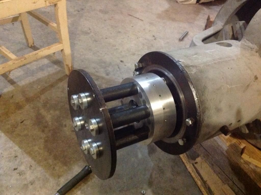
                                I thought I would post one last picture. ( jimboot, this is what will hold my coils, I have 1" between slugs at about 3 1/2 ". Lots of space.This is the stator, the steel slugs are fastened with 1" x 1/4 " bolts, so they are tight and I really do not need anything to stabilize the ends pointing to directors ( the name is stuck now dragon!).
                                The air gap at the magnet side is about 1-2 mm. Lots of flux transfer, there is only 1 group of five magnets, holding the stator head slugs to the directors.
                                I just have to cut my al pipe and secure the stator head to body.

                                Anyway, good luck to everyone building, and have fun !
                                Hopefully I'll be back in a few months, with my new motor spinning my new generator.

                                Last edited by machinealive; 01-03-2015, 05:43 PM. Reason: Spelling

                                Comment

                                Working...
                                X