Originally posted by machinealive
View Post
Announcement
Collapse
No announcement yet.
Topic: The new generator no effect counter B. EMF part 2 ( Selfrunning )
Collapse
X
-
Excellent work. Wish I had half your skill. Beautiful build. Nice bobbins too! Thanks for the vid, really helpful
-
Hi all,
I attempted to build an outrunner version of this type of generator. Since I have several variants of outrunners to choose from I thought that it would be easiest for me to modify and thus complete a test unit. Well, I have no funds or time available to work on this now.
So, I have taken it ias far as I can without finnishing this build. The reason for even posting this is that it may in fact be easier to work with for some who are sitting on the sidelines mildly interested, but not fully comitted to building from scratch or some other reasons.
With that all said, here is the build:
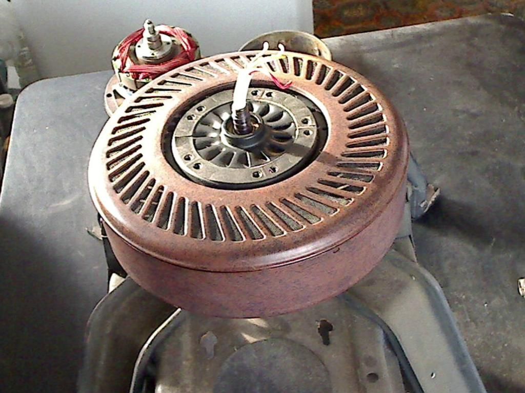
I had an old ceiling fan with an attached light kit that I decided to use as the base for this low lenz generator.

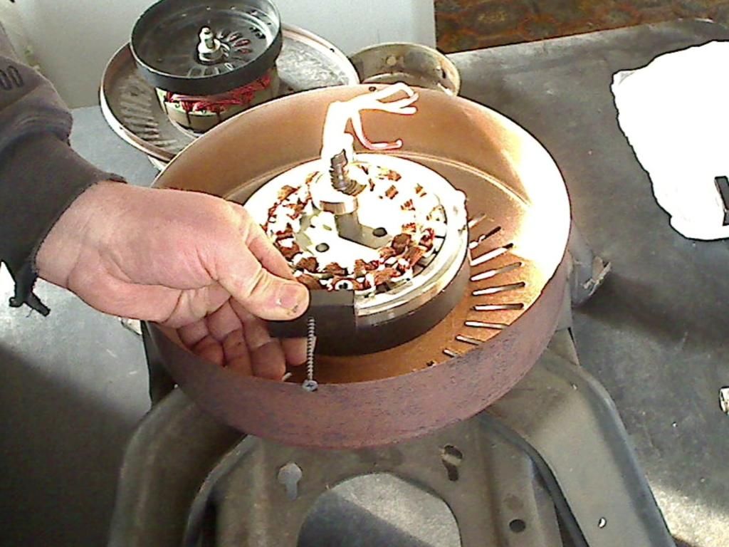
After taking the fan apart, i planned on attaching a steel pipe section inside the brown outer casing to hold some neo magnets, and to complete the magnetic circuit on the backs of the magnets.
Here you can see me holding one magnet sort of in the position I would have liked it to be in:

Anyway, I am completely unavailable for working further on this unit. If anyone wants to take this thought farther - GO FOR IT!
Also, I have a build thread over at http://open-source-energy.org/?topic=2326.0 that details most of what I had in mind.
Comment
-
-
Hi all,
Just an update. I've switched to a smart drive washing machine stator which a lot of guys are making wind gens from. It looks like about 22awg. Got the idea from Gerard Morins latest vid. Only thing is that the mags have to be on the outside diameter not the inside. Trying to work out how to remove the ceramic mags from the rotor without damaging them now.
Comment
-
Hi everyone,
I've been busy with another project for the past 3 weeks and didn't have the time to complete one of my last experiment to confirm if this effect has any value.
So before closing the book on this one, since my previous version was not showing a good results and was also a different design, I wanted to build a single coil version of Dragon's version since he claimed to have some good results.
Even with these changes, my results are not positive, however, I made a video of it anyways so all can see.
From all the replication attempts that I've seen, researchers are not doing power calculations (watts in and watts out), so as far as I'm concerned they won't see the reality until they do.
Link to video: https://www.youtube.com/watch?v=O0souZVPKw8
I'm moving on to testing Erfinder's multi strand bucking coils.
LucLast edited by gotoluc; 02-04-2015, 10:36 PM.
Comment
-
I will be sharing my replication attempt of Erfinder's multi strand bucking gen coils at this topic: Erfinder's multi-strand bucking generator coils
Comment
-
This was as far as I got when I decided to shelf the idea while it was so unbearable to work in a frozen shop. As soon as I clear the clutter I'll pull it out again and complete it.Originally posted by scot View PostHi Dragon,
How are you doing with this project I am very interested in building the same thing. Can I help you with yours?
Thanks, Scot
This is a remake of the small original tests and is ultra low cogging. I ended up remaking the entire rotor assembly and installed iron wire instead of silicon or solids... made a whole different machine.
I have a ton of projects in the works but as soon as I get the motor built I'll start posting more about it...
What are you working on in this area?Attached Files
Comment
-
Gen
Hi Dragon,
I just finished a hydrogen injector for Russ at RWG research.
I am a complete idiot when it comes to motors and electrical devices but I can see that there are some very good ideas to make generators more efficient.
I would like to help in the mechanical and machining area which doesn't help you much but I thought maybe I could get you some silicon steel.
Do you have projects that I could help machine parts for I'm kinda looking to trade help for help as I don't just want to just take without giving.
Thanks, Scot
Comment
-
Interestingly enough I was thinking of you a few days ago, wondering where you're at with the build.Originally posted by dragon View PostThis was as far as I got when I decided to shelf the idea while it was so unbearable to work in a frozen shop. As soon as I clear the clutter I'll pull it out again and complete it.
This is a remake of the small original tests and is ultra low cogging. I ended up remaking the entire rotor assembly and installed iron wire instead of silicon or solids... made a whole different machine.
I have a ton of projects in the works but as soon as I get the motor built I'll start posting more about it...
What are you working on in this area?
Thanks for the update and really looking forward to some test results.
Thanks for sharing
Luc
Comment
-
10kw 220v 50hz 1500rpm gen is convert to the new gen ,but the gen voltage is about 25v NO LOAD at 700rpm,the pm magnet is 100mm *50mm*10mm N52,arrangement NSNS,i dont know why the voltage is so low。
here is some pic。
Comment
-
Generating Fields...
Hello Aweiaini,Originally posted by aweiaini View Post10kw 220v 50hz 1500rpm gen is convert to the new gen ,but the gen voltage is about 25v NO LOAD at 700rpm,the pm magnet is 100mm *50mm*10mm N52,arrangement NSNS,i dont know why the voltage is so low。
here is some pic。
IMO I do not find 'suitable' your Generating Coils Fields arrangement versus your Four Pole Iron Segments, therefore, the magnets which are not seen on pics...
The Stator Generating Field overlapped coils are based on only two poles, while it has Four eight pole single coils, which seems for the exciting circuit.
Are you reproducing the Original Rotary Stator segments size circumference exactly as it was?
I see too wide gap between each iron segment.
[IMG] [/IMG]
In my opinion you will need the iron transfer cores to be matching the smaller size overlapped coils, meaning from two to four poles size from stator generator core, and not based on the four larger coils, which are not overlapped. That limits your continuous and increasing V generation.
Also, you do not need the "T" shaped laminated iron ...that is wasted space from solid magnetic field transfer, use semi arc rectangular segments. There is no wires going there...so, no need for that T shape. And make them not that deep, that is also 'delayed' transfer on the long run.
Just my two cents
Good luck there!
Ufopolitics.Last edited by Ufopolitics; 04-28-2015, 12:53 PM.Principles for the Development of a Complete Mind: Study the science of art. Study the art of science. Develop your senses- especially learn how to see. Realize that everything connects to everything else.― Leonardo da Vinci
Comment
-
first pic is for install pm magnets,
Comment
-
Sorry, but I do not think that would generate properly...Originally posted by aweiaini View Postfirst pic is for install pm magnets,
You have to keep the sweeping ratio Geometry, you have a 36 poles stator, that gives you @ -/+ 10º per pole (more likely around 8.5º), meaning each Magnet, and Iron Core MUST BE within at least, Eighty Degrees (80º) and having a gap between them of around 10º.
This Angles must be measured from shaft center to outer area.
Take a look at CAD below, then look at your design:
[IMG] [/IMG]
Hope this helps you...
Plus, you must realize you are using straight magnets (not Arc Segments), therefore you already have a loss in gap geometry transfer communication.
UfopoliticsLast edited by Ufopolitics; 04-28-2015, 02:05 PM.Principles for the Development of a Complete Mind: Study the science of art. Study the art of science. Develop your senses- especially learn how to see. Realize that everything connects to everything else.― Leonardo da Vinci
Comment
Comment