Announcement

Collapse
No announcement yet.

The Resonance Energy Device Explained

Collapse
X
 
  • Filter
  • Time
  • Show
Clear All
new posts

  • Originally posted by John.K1 View Post
    Just make sure it is possible to sweep the frequency. Once I bought some and and I was disappointed as I had to set desired frequency before sending to the output. You need SG where you can sweep the frequency during the operation!!! Just some advice

    Hi John,

    yes i can change the frequency but the range of frequency is relatively low, for example changing the discharge capacitor in NE555 module to 500 pf the frequency go to 50KHZ i can vary this frequency to 20KHZ even though my system resonate at 26 KHZ but in high voltage the system start responding below 20 KHZ !!! i don't know why this happen ??

    Comment


    • Originally posted by med.3012 View Post
      Hi John,

      yes i can change the frequency but the range of frequency is relatively low, for example changing the discharge capacitor in NE555 module to 500 pf the frequency go to 50KHZ i can vary this frequency to 20KHZ even though my system resonate at 26 KHZ but in high voltage the system start responding below 20 KHZ !!! i don't know why this happen ??
      Hi Med,

      I do not fully understand what you mean in HV system responding at below 20KHz. How do you measure this? Possibly measurement error?

      Comment


      • Originally posted by John.K1 View Post
        Hi Med,

        I do not fully understand what you mean in HV system responding at below 20KHz. How do you measure this? Possibly measurement error?

        i agree maybe i did some mistake, i just applied the resonance frequency in low voltage and see the respond using a scope, at 26khz peak to peak was at max about 12V , now using the same NE555 oscillator to feed a MOSFET which drive a flyback TV transformer the resonance can't be achieved at 26KHZ, i used a neon light bulb as indicator, the scope show the frequency in the primary of HV transformer was correct but no respond from HV side, when trying to see the respond in high voltage the system start responding at 20 KHZ which mean i have a problem

        Comment


        • $49

          Originally posted by med.3012 View Post
          Hi BroMikey ,

          thanks so much for your post but Ebay don't ship to Algeria and i know the reason !! we have a bad custom service here, especially when the product is electronic part, i have a bad experience with them


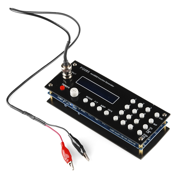
          How about these guys for $49?? Don't give up.


          https://www.sparkfun.com/products/11394


          Generates continuous waveforms of Sine, Square, Triangle, Ramp (up and down), and Staircase (up and down)
          Generates servo test/control signals in micro-second resolution with user programmable pulse width, amplitude, and cycle
          Set the frequency (or period), amplitude, and offset with number pad - quick and straight-forward
          Frequency (period), amplitude, and offset can be incrementally adjusted with rotary encoder
          Settings are memorized after power down
          Can be used as an adjustable DC voltage source by setting amplitude to 0
          Frequency range: 0 - 200KHz (Sine)
          Frequency resolution: 1Hz
          Period resolution: 1ms
          Amplitude range: 0 - 10V peak-to-peak
          Offset range: -5V - +5V
          Memory depth: 256 bytes
          Sample rate: 2.5Msps
          Output impedance: 50 ohm
          Power supply voltage: DC 15V
          Current consumption: < 150mA (without loading)
          Dimension: 155 X 55 X 30 mm

          Comment


          • Hi Mickey,

            In the similar price range I can recommend this one :

            10MHz DDS Function Signal Generator Module Sine Triangle ​square Wave TTL Sweep | eBay

            Works fine for me. Sine, Tringle, Square 9Vpp 10MHz max, real time sweep unction.


            Or you have other option - combination of Arduino and AD9850 - which gives you around max 60MHz - but you need to program it, which is not a big deal

            AD9850 DDS Signal Generator Module 0 40MHz IC Test Equipment Sine Square Wave | eBay ................€10

            Arduino Compatible UNO R3 Board ATMEGA328 ATMEGA16U2 With Free USB Cable | eBay ...............€10
            Last edited by John.K1; 09-23-2015, 10:09 PM.

            Comment


            • Today is the celebration of Eid al-Adha this is the second of two religious holidays celebrated by Muslims worldwide each year, wish the best for all !
              Last edited by med.3012; 09-24-2015, 09:25 AM.

              Comment


              • Hello everyone,

                at the moment no new experiments, so just to share an old video i made about radiant discharge, the light came from the capacitor is very strong and it may hurt the eyes !! i was speaking with my native language, it's a few word telling this is the second experiments.


                [VIDEO]https://www.youtube.com/watch?v=K89T0mPoTYE[/VIDEO]


                https://www.youtube.com/watch?v=K89T0mPoTYE


                EDIT :
                in the above video it's not easy to see how strong this light was, so this is a snapshot at the right moment, in real experiment the light look like a ball of light ! it was able to light a dark room with easy !!

                again this is very danger for eyes !


                Attached Files
                Last edited by med.3012; 09-26-2015, 01:37 PM.

                Comment


                • Hi Med, Not sure what you want to say with that spark. Any strong spark makes bright light- that's why welders use the mask

                  Just a question which might be related to this topic too. Imagine you have a Tesla coil and its top capacitor (in our case couple turns of thick wire- lets call it antenna) is wrapped around your EEBC. Nothing special so far. Now, there is a guy Akula, who puts the variable induction between Tesla coil and this antenna. He is saying that that tuned induction change the sinus (as we expect) in to the sharp face pulse, which might shoot very high in many KV.

                  Is it possible?? This is basic principle of (possibly) working Ruslans and Akula device. They do not use ETBC, they use the capacitor/coils to collect that energy. I just think ,instead of use cap/coil, I can use ETBC Ofcourse, Tesla and ETBC must work on the same frequency.

                  Comment


                  • Hi John,

                    Thanks so much for your interest about the technique used behind the E-TBC, maybe i am specialized in the principle working of the E-TBC, so i am not professional outside the E-TBC !

                    the first technique used to feed this device from CD junction as spark gap gave us a bad results, this is why we must use this device as oscillator primary coil, the E-TBC is the rector coil where the energy is amplified and after that replicated with radio frequency speed.

                    so it have to work inside a resonating system which provide some kind of high voltage even if CD is short circuited... things aren't easy as they appears, the working principle of ordinary Tesla coil is a bit different than the requirements of our E-TBC! the E-TBC need a normal hot ordinary high voltage between AB even if CD is closed that's all !! believe or not ! over energy will be produced in large amount !!!!

                    if you give this requirement to this device a lots of amazing things will happen, this is the most perfect and easy way to produce electricity not only this !!! it's also the most cheap !!! this is because any required power can be produced theoretically, remember the mixed E-TBC is waiting !!!

                    as i understand the E-TBC we have to work with heavy electrons and then pass to multidimensional transformer when this happen everything will be related to particles spin, what we know as voltage and anti voltage are nothing than a power and its killer which is known as electric currents, the notion of electric power is totally wrong !!

                    i can't answer your question because i don't know what kind of power will leave Tesla coil you use, so i can't expect the respond of E-TBC !!

                    tell more about your idea maybe we will find a solution

                    Comment


                    • Hi Med.

                      Thank you for your answer. On the picture below is what I am talking about. I am not sure what you mean normal voltage. Capacitor generally store the potential energy and one of the way is to charge it by radiant energy. I will be honest with you, I do not fully understand your view of the ETBC but your explanation sounds very professional so I do believe you

                      Not sure where the extra energy comes from to your device. I am pretty sure you have explained it here before. Just I need to read it couple times Don't you need some current flow? It means some sort of load. Where is the point for that load? How do you collect energy from your ETBC and not destroying the process?

                      Let me tell you something. There is a lake with the boat(s) on one side. The question is how to get the boat(s) on other side with least energy implied. Ropes are not the solution. Now imagine you have found the plug on the bottom of that lake. Minimum force to pull plug cause a water to flow ,so does boat(s).

                      Some people says the grounded Tesla is that plug. Properly tuned Tesla coil does radiate inverse - in to the capacitor and goes to the ground. The receiver(s) around, they are just in the path of that flow- the energy flows through it. What that means? -We used minimum energy to open sink (ground) and collection of the enormous energy is available as the flow.

                      Attached Files
                      Last edited by John.K1; 09-26-2015, 08:16 PM.

                      Comment


                      • Just to share some results from the measurement of the resonance of ETBC.

                        Generally I couldn't read some massive peaks. But as you can see FTT analyzer shows some harmonics every +/- 2MHz
                        Attached Files

                        Comment


                        • Hi John


                          you are welcome , the principle work of E-TBC is based on attracting ambient electrons by providing an extension of ordinary wire form a normal Tesla Bi-filar coil, so instead of normal thin wire we just use a large conducting foil at this point it's easy to understand this but in dynamic state everything is related to each other in a very complicated manner...

                          it took me a long time to understand how this device oscillate, a friend to me asked me several times how the E-TBC oscillate? frankly i wasn't able to give a perfect answer even after discovering the 1D capacitor and after expecting the double frequency behavior ! i was right about double frequency phenomena but how the E-TBC oscillate was a big problem, fortunately another friend send me his point of view about serial resonance !! this took some months from his time to see this amazing phenomena, i give the honor of this discovering to him even though in my presentation i showed how the imaginary E-TBC is formed.... where the junction CD was re-opened.. , my friend was working in base tension system providing a kind of timing to open and close the junction CD at the same frequency of the E-TBC he was working with, so his idea is to open the junction CD to provide the serial resonance at the right time ... unfortunately he is very busy to provide more details ...

                          at this moment i went back to Tesla patent to catch any hidden words that may help me, as you know it's the most difficult work to look after Tesla cryptography, frankly i wasn't able to discover more secrets only some indications, for example the ability of this device to produce Ozone gas is related directly to the capacitive foils, if you see Tesla patent about producing Ozone gas you will see a simplified serial resonating E-TBC, Donald Smith stated the same thing about the ability of his device to produce such gas!

                          serial resonance inside the E-TBC is the other half image so the complete energetic picture can be seen, this device is able to produce double frequency because it work in the half image so it's not overweighted, if you add the serial resonance image it will be overweighted and the frequency go down to normal equation!! this happen when we form the capacitor faraway from the coil, nature will look for the equilibrium by loading the system so magnetism will be taken from electricity and not conserved as the E-TBC do ... in the E-TBC the capacitive side will say to the magnetic field : whatever what you take it will be returned to me by the induced electric field you create the magnetic field will go angry and increase more and more while the capacitive side is resting and taking more power !!! these conserved charges are responsible for the passage to serial resonance which is nothing than spin separation mechanism current and voltage are nothing than spinning particles, at this moment the E-TBC form a no polarized device! the CCW foil appear to be a CW from behind! right ?! so the particles in the positive charged plate will only change its spin direction to appear as a pure negative particle since the E-TBC give this opportunity!! the particle from each side will just send this message : don't move we will just change the spin rotation everything is prepared ! this is the moment when the Ozone gas will be produced if you don't believe see again Tesla patent ! this moment is the time when active energy is produced since the magnetic field is in its pick and the electrons passage will produce the needed radiant electric power, here the voltage will be radiated and this explain the very high level of excitement which produce Ozone gas...

                          this principle lead me to think not to confine this device by another resonating system at the same frequency.. i hope you understand me at this point ... this device form a mixed of static and dynamic charges moving in very defined timing provided naturally, so the idea is to give only a high frequency DC pulse and let the device resonate at its own way ...
                          Last edited by med.3012; 09-27-2015, 12:05 AM.

                          Comment


                          • in this post i will propose the basic idea about c1/c2 system, later i will show the practical usage for it, for me it was the most easy system that enable me to see the resonance of E-TBC, the test was simple; just connecting C2 to the E-TBC ( CD was closed ) and then removing it to test if the E-TBC is able to handle the power without external source the answer is YES! the power is there for a long time, i tested this using a small neon light bulb but due to the number of test this device lost its power very soon, faraway from what i did i will just show the basic behind c1/c2 system, here you are the drawing :


                            the idea is to benefit from the electric field inside an ordinary capacitor by inserting another two isolated conducting plates, in other words inserting an inner capacitor inside the primary capacitor c1, the high voltage dc pulse have to be attached to c1 so the electric field will flow from the positive plate to the negative plate, the same field must pass through c2 and charge it to the same high voltage value without direct connection, the distance between the capacitor plates of c2 help in this since it's smaller, let give it the value d2, smaller distance mean higher electric field value so a reasonable high voltage can be built without direct wire! when c2 is short circuited c1 is still able to give a high voltage discharge across any spark gap used for this experiment! the problem with this system is it work better in high voltage, i guess low voltage will not give a good result. further detail about this system will be provided soon, this system is important because if we feed the E-TBC using c2 the primary source c1 will not be degraded totally ... this give the opportunity to achieve the resonance without great effort, i am not able to test it now because my primary prototype was lost! i have to build another prototype
                            Attached Files
                            Last edited by med.3012; 09-28-2015, 11:25 PM.

                            Comment


                            • Completing the discussion about C1/C2 system now it's the time for practical issue, you need two plastic tubes wrapped with aluminum foils, these tubes have to be slightly different in diameter, or just choose a random diameter tube, cut it into two identical size, the bigger one must be cut along its length so it will be easy to slide the inner tube inside this one ( the bigger ), take the inner tube and wrap the first capacitor plate, isolate it very well, you need a connection to it with a well defined wire color, now you have to wrap the second plates on this inner tube do the same with another wire, choose another color. now please take a look at the following simple drawing :


                              the bigger tube is the same as the inner, in the above drawing the important is to make two different capacitors, C1 is connected directly to the source power, c2 will be charged statically using the electric field, the source power have to be a transistor oscillating circuit as this will give a higher frequencies :


                              also it's better to use two TV flyback high voltage transformers connected in parallel as this will give an amazing performance, the capacitance of c1/c2 system is relatively low, in practice they are in order of a few hundred picofarad .
                              Attached Files

                              Comment


                              • Originally posted by BroMikey View Post
                                How about these guys for $49?? Don't give up.


                                https://www.sparkfun.com/products/11394


                                Generates continuous waveforms of Sine, Square, Triangle, Ramp (up and down), and Staircase (up and down)
                                Generates servo test/control signals in micro-second resolution with user programmable pulse width, amplitude, and cycle
                                Set the frequency (or period), amplitude, and offset with number pad - quick and straight-forward
                                Frequency (period), amplitude, and offset can be incrementally adjusted with rotary encoder
                                Settings are memorized after power down
                                Can be used as an adjustable DC voltage source by setting amplitude to 0
                                Frequency range: 0 - 200KHz (Sine)
                                Frequency resolution: 1Hz
                                Period resolution: 1ms
                                Amplitude range: 0 - 10V peak-to-peak
                                Offset range: -5V - +5V
                                Memory depth: 256 bytes
                                Sample rate: 2.5Msps
                                Output impedance: 50 ohm
                                Power supply voltage: DC 15V
                                Current consumption: < 150mA (without loading)
                                Dimension: 155 X 55 X 30 mm


                                Using the ancient 16F84 and XR2206, can build yourself this:https://www.youtube.com/watch?v=6ZUecmRnAYA
                                the source code on the link above

                                Comment

                                Working...
                                X