Announcement

Collapse
No announcement yet.

Bucking Coil Inverter

Collapse
X
 
  • Filter
  • Time
  • Show
Clear All
new posts

  • Hi darediamond, the partnered secondary coils are wound on the core first, then bifilar oscillator is wound over one half of core, on top of secondary.
    The direction of secondary winding under the primary will not matter, as they are induced coils.
    Though one of the secondary coils is wound in opposite direction, in relation to other secondary coil.
    Each secondary coil is only a single wire coil.
    peace love light

    Comment


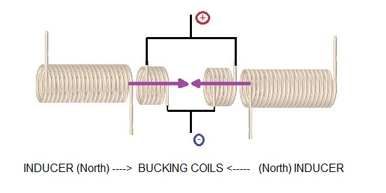
    • Look how Daniel Dingel seems to had arranged his coils in his water powered car. A perfect bucking coil system. The two inducer coils are in repulsion (one is CCW and other CW)


      Suppose two primaries and two secondaries coils in the middle of the primaries. If the primaries are in attraction mode the only field transversing both secondaries is:
      N ---------------> S. As per Lenz, the induced field of each secondary will be <-------- in one secondary and <-------- in the other secondary. Both opposing to the primary field. How are you going to buck both secondaries fields? Impossible. No way

      If the primaries are in repulsion their fields will be N -------> <--------- N . In this case one secondary will oppose to its closer primary field: <-------- and the other secondary will oppose to the primary field of the other primary coil: -------->. There you have two bucking secondary coils. Perfect bucking output coils. In this case you may use pulsed DC. You just need to collide two fields in the center point, right in the point between both secondaries coild, no need for movement of the fields in this design based in flux linking.

      Summary :

      Attraction N ------------------------> S
      ..................<--------... <---------

      Repulsion N ----------> <----------- N
      ..................<---------... --------->

      If two inducers are placed in repulsion and two induced coils in between, then each induced coil is just transversed by one inducer field, the one from the nearest inducer. That's the key. Both inducer fields collide in the center in a point between both induced coils and are expelled from the core. Therefore each induced coil is under the action of one inducer field. The two induced fields, which oppose to each inducer field, will be bucking each other <------------ -------------> . With vectors : B1induced + B2induced = 0 . I have not tested it, but theoretically it is a perfect bucking system.


      Repulsion N ----------> <----------- N (inducer fields)
      ..................<---------... ---------> (induced fields)

      https://figueragenerator.wordpress.com/

      Comment


      • Originally posted by SkyWatcher View Post
        Hi folks, its a straight ferrite sleeve, and the coils are wound like wistiti's video.
        One bifilar layer 24awg., then on top, the 30awg. partnered coils.
        Like i said, compared to just using the induced partnered coil output, it is using less amp draw and lighting the led bulb to same brightness.
        So it seems more efficient by placing the series partnered coils in parallel with the primary winding.
        The diode didn't seem to help any in my setup.
        peace love light
        Sky,did yountry the Son Smith 1/4 wavelength auto resonance winding of the Primary and secondary?

        Comment


        • If some of you still playing with POC(bucking coil), you may find it interesting...

          https://youtu.be/v9aiyfsMRw8

          Comment


          • ....

            ....seem no one are interesting on it....
            sorry for sharing it here...

            Comment


            • Hi wistiti, thanks for sharing.
              I will look at it closer.
              Can you share a circuit drawing so we all know exactly how the diodes and the rest of the circuit is wired, also for people that aren't familiar with this setup.
              Thanks.
              peace love light

              Comment


              • Hi Sky,
                Here is a quick hand draw of the circuit show what is working and what is not.

                What I want to show here is there is a way to rectify the bucking coil output so it assist the primary and reduce the input power when under load... this happen when using pulsed dc as input...

                When people know that, it is up to them to build and experiment with different way a pulsing primary can be (mechanical, solid state, same pole magnet, etc...)

                I have nothing more then to show then what I have share. I do it on this tread cause is where I firstly see it on your tread and I thank you for opening my eye on it.

                Hope you the best!
                Attached Files

                Comment


                • Hi wistiti, thanks for sharing the circuit drawing.
                  It looks like the diodes are conducting, when the secondary coils induced field collapses, in the check marked drawing.
                  What i would like to see and try, is test the same thing, with the two diodes, though only using one continuous wound secondary coil, over the primary.
                  This, to see if the input decreases on load, in the same manner as the setup you are showing.
                  I think i will try it first, with the continuous wound secondary, all in same coil winding direction.
                  peace love light

                  Comment


                  • Hi all, Hi wistiti, i wound the coils and used the same ferrite tubes as i used on previous test setup.
                    I used 24awg. magnet wire bifilar directly on top of ferrite tube, used as joule thief oscillator.
                    Then wound 24awg. magnet wire secondary coil over entire top of bifilar coil.
                    Used 9 volt wall wart, connected through killawatt meter as input.
                    Used 12 volt led bulb as load, this bulbs input circuitry is non-polarized.
                    I used two diodes as you have shown, then tried them both ways across secondary coil and did not observe any significant change of input watts.
                    I will now rewind the secondary as partner coils, with one wound in opposite direction.
                    peace love light

                    Comment


                    • Bucking coil inverter thread had over 55,000 hits because it is a topic that
                      people are interested in. Sometimes the participation level goes down like a hobby trend.
                      Those who regularly participate get to be friends that is important.
                      The relevant information needs someone to focus and refocus
                      organizing the details in a pdf also informing those new that want to
                      understand and it takes a lot of patience. I think it will go higher and get better because
                      the popularity has been a natural trend.

                      Comment


                      • Hi all, i tested with the partnered output coils and did see a difference.
                        With the normal continuous secondary coil, input was showing around 1.7 watts, with diodes both ways.
                        With the partnered coils, one way shows input 1.7 watts and the other shows 2 watts, the brightness of led bulb in all tests looked very similar.
                        Hmm, not sure what to make of these results, any thoughts wistiti.
                        peace love light

                        Comment


                        • Hi Sky.
                          Not sure why you have such results.. maybe it’s the frequency... you may also try to reverse the polarity of your diode to see if you have a difference... also, my POC have more turn then my primary. Like 1 to 4 ratio.

                          In my experiment, the primary, even with no secondary over it is runing at around 3,6w. When the POC conected the right way, power drop to 2,9w.

                          Hope it help.
                          Last edited by Wistiti; 03-06-2018, 12:31 PM.

                          Comment


                          • Hi wistiti, i was thinking the same things, frequency or the fact that the winding ratio, since the partner coils are in parallel, works out to a 1:1 ratio.
                            Since the oscillator primary would only fill half the core and so does one partner coil.
                            Ok then, i will rewind the partner coils, like i had it originally, using 30awg. magnet wire.
                            What wire gauges are you using for oscillator and partner coils?
                            peace love light

                            Comment


                            • Not sure but something like 23awg for the oscillator and around 30awg for the POC. Make sure to mesure the wattage for running it before connecting the poc at any maner. This way you will have the real consumption of the circuit with no load. After thAt connect the poc between them and play with the diode until you see the effect we are looking for...

                              When it happen it take a little delay before the load goes on ( like the first time I on the circuit in my last video) also , if you can eard the effect build up...

                              I think it is the time it take before the different magnetism in the core (3 coils) find a way to work together (EMF, BACKEMF, etc...) it take around 1second to build up...

                              Ciao!

                              Comment


                              • Hi wistiti, in the video, you showed what looks like a small incandescent bulb, what is the voltage rating on that bulb.
                                That may be important also, because if it's a 12 volt bulb, that means the partner coil output voltage is being pulled way down.
                                I think i will try some different loads, like resistors, then the non-polarized 12 volt led bulb and see any differences.
                                Ok, going to start winding the 30awg. now.
                                peace love light

                                Comment

                                Working...
                                X