If this is your first visit, be sure to
check out the FAQ by clicking the
link above. You may have to register
before you can post: click the register link above to proceed. To start viewing messages,
select the forum that you want to visit from the selection below.
This is a unique system that will grant you a huge deal of electrical independence. You will save more than 80% from your bill every month. It can be built with simple materials with a cost as low as $100. It will work all year long, and much more, so that you do not have to worry or keep investing money on it. More than 30.000 families have already benefited from this product. Now it is your turn!
This video explains how magnetism is actually caused by the Magnetic Spin Vortex. It covers what the spin vortex is, and it is not, and the importance of understanding it in the field of Permanent Magnet Motive Force Systems.
The Magnetic Spin Vortex
I posted a simple comment on that youtube page - pump the bottom one with the top one up and down and NOT side by side. I spent countless hours over 3 months on these spinners before I ever tried to build the original SG - that was 16 years ago.
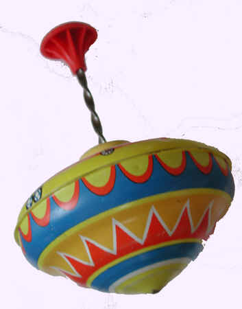
To me, it is like this toy but magnetically - that is what I found anyway:
I posted a simple comment on that youtube page - pump the bottom one with the top one up and down and NOT side by side. I spent countless hours over 3 months on these spinners before I ever tried to build the original SG - that was 16 years ago.
To me, it is like this toy but magnetically - that is what I found anyway:
Hi Aaron
I must be thick because I do not understand your comment. But I am
having flashbacks of Xmas 1963. Just kidding had to throw that in
because I buy the children a top when I can still find one.
I have always loved to watch a top spin, still do. I have been thinking
about John's concave rotor magnet assemblies from the conference
2010 Ferris Wheel bright red saying something like this to the audience
"You want to know why you don't have what I have here in this example?"
The magnet spin vortex and the SG have always intrigued me. I would
love for you to explain anything about this post more clearly as it directly
relates to both magnet motors AND those awesome coils with their
own capacitance.
Here is one to ponder. Youtube. Insane accidental discovery with neodymium maqnets. Free energy? After you calculate the energy needed to lift that stack of neos, then calculate how much energy is used to keep it running, I think this could qualify as a free energy magnetic motor. Simple, functional and efficient. All we need to do is build a large one big enough to draw energy from it. Good Luck. stealth
Here is one to ponder. Youtube. Insane accidental discovery with neodymium maqnets. Free energy? After you calculate the energy needed to lift that stack of neos, then calculate how much energy is used to keep it running, I think this could qualify as a free energy magnetic motor. Simple, functional and efficient. All we need to do is build a large one big enough to draw energy from it. Good Luck. stealth
Hey Stealth
I see the top but I do not understand how neo's play in. Do you have
a video link?
I spent countless hours over 3 months on these spinners before I ever tried to build the original SG - that was 16 years ago.
In 1997 when that video was made I was 40 years old. So you were 24 years then? The old picture. Time flies when you are having fun.
What stood out was the idea of a "ramp" these motor schemes all use
some form of a "RAMP" be it made of metal or magnets. I am just now
seeing how a wide variety of "RAMPS" are used in many motors.
The picture "GIF" animation above is like most proof work only showing
one piece of the larger puzzle.
Rotors = 3:1 (The mini are 1/3 the diameter of the big rotor = .33)
12:4 = 3:1 (Number of Magnets)
45:15 = 3:1 (The rotors swap neutral every 15* and every 45* they reverse direction on the graph)
90:30 = 3:1 (Magnets Spaced) (90* out of a 30* clock = 60, 45 and 15 sec)
180:60 = 3:1 (Equilateral Triangle) (60 60 60) 666
360:120 = 3:1 (Mini Rotors Placed)
3:1 timing belt is probably required! (Disconnect capacitor drive)
Mueller / RomeroUK with New Magnets, Neodymium 8 Magnets, of 2 x 20 mm Diameter x 10 mm Thick, as Motor Only.
2 x Coils as One Coil for Motor, 2 x Coils as One Coil for Trigger.
The rest of the Circuit is yet Bedini Style, the Red LED is Lighted when the Motor Coils are Powered, Negative Rail on Oscilloscope, the White LED is Lighted on Collapse EMF and Generator of the Motor Coils, the Positive Rail on the Oscilloscope.
Components :
- Transistor : Silicon NPN 2N4401
- Diodes : 1N4148
- Coils all 4 Coils are 0.2mm Emaeled Copper Wire, about 12 mH each.
- Cores : 2 x 9 Ferrite Cores, 5.5 mm diameter about 60 mm Length
- Magnets : Neodymium 8 Magnets, of 2 x 20 mm Diameter x 10 mm Thick, N52
Characteristics :
- Motor Coils work in Attraction Mode
- RPM : 40 Hz / 8 = 5 Rotations per Second so about 300 RPM / Rotations Per Minute
- Operating Voltage : 12 Volts
- Power Consumption : not measured yet
--
Update / 2015-11-23 21:06 :
- Power Consumption : 58 mA @ 11.58 Volts so about 0.67164 Watts ~ 670 mili Watts.
With a "Better Version" of Command : 2 x Monostables, 2 x Motor Coils and 8 mm Diameter Magnets I got ~ 72 mili Watts, so, as it is this is way worse.
Let's see it when the PIC Commander will be in effect. Stand by...
Amigo the party is just beginning so don't miss this one.
His work is based on the Howard Johnson stuff
The man says he is not going to be on youtube anymore
because people are calling him a fake and attacking him at
overunity. He made the excuse that humanity must not be ready
for this break through.
he was Not a fair player and was caught with a "string/thread" drive
in the Vid [I think Tinsel found the spot where you could see it ...
might have been member Wattsup at OU.com ??
 Tweet
Tweet

 Just kidding had to throw that in
")
 Here let me give you what you want


Comment