Announcement

Collapse
No announcement yet.

Mikey's Beast SSSG OSCILLATOR

Collapse
X
 
  • Filter
  • Time
  • Show
Clear All
new posts

  • #76
    Nice circuit Bro Mickey
    Just want to know what is the crow bar circuit function.....???

    My target is to use less solar panel in my house and apply ur circuit with sssg

    so i m following ur design development ....... thanks

    Comment


    • #77
      Originally posted by totoalas View Post
      Just want to know what is the crow bar circuit function.....???


      4 Crowbars.

      Crowbar1=12.8v

      Crowbar2=13.5v

      Crowbar3=15v

      Crowbar4=73v safety shutdown

      Hey Totoalas

      Crowbar is the same for all (ALMOST)

      Crowbar is voltage control the way you like it.

      When batteries are properly charged input power levels
      are turned down at different voltages.

      For instance if I run my inverter hard for 2 days and my battery
      is 12v, I have a dead battery. The inverter pulled my battery down
      to 10.5v and now it is very low.

      The sitting voltage with no load connected is 12v, empty battery.

      Now I must charge the battery hardest up to 12.5-12.8v.
      This means that my charger is working on high and is putting
      max into the battery.

      Let's say your SSSG can deliver 800 watts max but you only run 500watts.
      So 500 watts is going to the battery to charge it back up again.
      This is "high"

      When Crowbar1 reaches 12.8v the circuit drops a resistor.

      So now your SSSG is running on "medium". Maybe only 400 watts. Now less power in going to the battery. Soon the battery will go from 12.8--to--13.5v
      and crowbar 2 will drop another resistor out of the trigger of the SSSG.

      Now your energizer is in "low" from 13.5--to--15v full.

      So we have "HIGH", "MEDIUM" and "LOW"

      In low the SSSG is only 300 watts or whatever you want it to be.
      Now you have 3 crowbar controls to charge your batteries with
      so you don't hurt your battery.


      NUMBER 4 CROWBAR never works, it is there only if
      the battery is broken or disconnected. You don't use crowbar 4 it is
      for emergencies.

      Crowbar4= 73 volt shutdown of SSSG energizer. In case a battery plate
      gets broken and the voltage rises to high. Also if your cap dump
      stops and the caps keep filling up past 50 to 60v the crowbar4 shuts off
      the power so you do not hurt your cap dump circuit too.

      Whatever energy project we choose, the battery must be charged and this is the best way to charge a battery.

      Good to see you.

      Mikey
      Last edited by BroMikey; 06-21-2015, 04:09 AM.

      Comment


      • #78
        thanks Mickey

        great stuff .... thats the future of SSSG and ure right dont know of somebody except Patrick working on this development

        totoalas

        Comment


        • #79
          Originally posted by totoalas View Post
          thanks Mickey

          great stuff .... thats the future of SSSG and ure right dont know of somebody except Patrick working on this development

          totoalas

          Okay thanks 4 the heads up on PK. I didn't see Patrick's stuff yet. Maybe I'll
          have a look. Glad to see somebody wants the safety controls besides me.

          Mikey

          Comment


          • #80
            It is important to have an automatic shutdown circuit so I have
            been looking at a few different ways of doing that.

            The simple way is the LATCHING RELAY. It needs
            a start button and the Crowbar could be the stop.

            I will show this in the next drawing in the days ahead.

            I will use this in the same circuit I have.


            Comment


            • #81
              In this diagram I have used a latching relay.
              This latching relay with momentary reset
              button solves the issues of using both GenMode
              or Spike mode and still have a limit control.

              This also lets experimenters use common
              relays without having to special order.

              Follow the 6 pin connection pathways and I
              think you will find that this one is best. I
              still need to add the LED indicator lights.

              Will update soon. This is my favorite ski-matic.

              As a for instance my 7 year old and my 11
              year old will be plugging this Energizer
              charger into their scooters and if they do not
              properly push the plug in all of the way, when
              they hit the reset button the charge will stop
              instantly.

              Or lets say the 7 year old runs up and rips
              the cord out of her scooter of course being
              in a hurry to catch one of her favorite friends,
              then the unit still shuts off.

              For scooters I intend to only use Gen-Mode most
              of the time with only periodic Spike-Mode
              conditioning, no cap dump.

              I have used GenMode for a couple of years now
              and the scooter batteries do well. Cold boiling
              to 31vdc is the way to go.

              Well I forgot to remind everyone that all of my
              scooter batteries are converted daily to ALUM.
              I wouldn't give you a nickel for a gallon of ACID

              My limit will be set at 31volts for shutdown and
              2 other power level changes for cutting back
              current as the charge cycle nears its end.

              This diagram looks at the cycle end voltage of
              31volts in the case of filling a 24volt battery pack
              or it could be used as a 73volt limit for a capacitor
              discharge bank. This way cap dump mosfets are
              protected from over voltage as well as possible
              damage to the caps.

              This is a fail safe function making it impossible to
              fail unless you hooked up something backwards.

              We will get to the reverse voltage protection as
              needed. In the case of the tiny scooter energizer
              I plan to use a one way plug system as is normally
              the right way.

              On the other hand for one of my desktop models
              with gator clamps I will want the reverse protection.

              This is my gift to you who want protection like I do
              and control as is used in industrial units. For those
              who do not have time to design circuits like this
              and might not be sure how to start.

              Super computers have there place and this is not
              one of them.

              Scooter chargers sit out in the pouring rain

              Enjoy.


              Last edited by BroMikey; 05-07-2015, 01:37 AM.

              Comment


              • #82
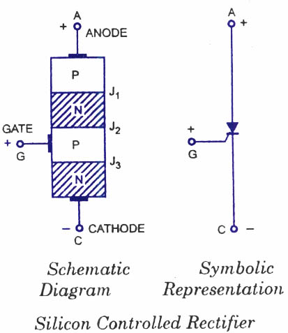
                How does this crowbar circuit works ? Is it working due to thyristor current reaching 2mA level and opening thyristor ?

                Comment


                • #83
                  Originally posted by boguslaw View Post
                  How does this crowbar circuit works ? Is it working due to thyristor current reaching 2mA level and opening thyristor ?
                  I think that is what the data sheet says, the important thing is that it opens
                  wherever I set the voltage on the meter, so in this case 31v is what I want.

                  I tested this dozens of times and the circuit operates the same every time.

                  When I read the Data Sheet it is like most all SCR's stating a minimum voltage and a minimum ma range. Then this is based on the gate resistance.

                  For instance for sensitive gate SCR's we need 320,000 ohms of resistance
                  to do the same job opening at the said voltage as the general purpose type that only need 25k.

                  So it looks like the sensitive gate needs approx 10X more resistance in the gates than the non-sensitive gate. Both work the same, no problem.

                  All transistors and other semiconductor junctions work at their specified
                  voltages and ma ranges.

                  Do you have a question about one of your parts? Or perhaps you
                  have a circuit to show us?

                  Look at the gate resistor and vary it to make it adjustable. Say you wanted
                  18volts then you would decrease the gate resistance so it opened before 31volts.

                  The cool thing about the SCR is that once it is latched it stays latched until
                  the gate voltage drops to under 500 mili-volts. You have to cut the power to reset. Mosfets and transistors do not display this characteristic that I am
                  aware of without special designs.

                  This crowbar consists of a single SCR and a single gate resistor.

                  Mikey
                  Last edited by BroMikey; 05-06-2015, 08:14 PM.

                  Comment


                  • #84
                    Here is a typical understanding of an SCR


                    https://www.youtube.com/watch?v=ItSwgq3M0Eo


                    https://www.youtube.com/watch?v=eGgamlfaVxI


                    https://www.youtube.com/watch?v=kmscJdu0oW4


                    Last edited by BroMikey; 05-07-2015, 01:52 AM.

                    Comment


                    • #85
                      Here is a scooter diagram. In the picture you can see a direct
                      connection from the batteries to the power module. I would have
                      liked to pulse my scooter batteries but I dare not for fear of
                      ruining the electronics as power surges destroy components.

                      I have heard of people pulsing at 2volts above battery voltages
                      to keep damaging surges to a minimum. I think the best solution
                      is to have some sort of bus bar dummy link that can be pulled
                      during a surge charge.

                      If possible I would like to hear any ideas on this so I may also
                      speed pulse charge. The scooters are getting more attractive
                      with some of them running 36volt motors.

                      I'm just not sure how much pounding these systems can handle.

                      John B stopped pulsing altogether and uses a form of GenMode
                      splatter in an AB series shunt regulator amplifier energy right off
                      the crystalline junctions. No coil either.


                      I like pulsing batteries.

                      https://www.youtube.com/watch?v=0fPCOeWWrrs


                      Last edited by BroMikey; 05-07-2015, 03:06 AM.

                      Comment


                      • #86
                        I finished the build of this circuit today and there was one error
                        that I have corrected where the reset button went.

                        Other than that the circuit does work perfectly as compared
                        to diagram produced by a circuit generator, this one is tested.

                        I will post a video soon and some pictures. The control module
                        takes up a 2" X 2" space on a PC board and is only one of 3 or
                        4 such circuits adjusted at various settings on a single battery
                        charge controller.

                        This is my first built and tested 73 volt shutdown crowbar
                        with latching relay. Once the start button is hit to charge
                        your battery it immediately shuts off if the battery plates are
                        not absorbing the energy or if a battery charge terminal
                        has fallen off.

                        This 73volt figure is used because the energy will also be
                        going to a cap dump where caps will top out at 60-65v.

                        I am filling a 400volt 1500uf capacitor to 73 volts at which time
                        the circuit shuts down.

                        Sweet success.


                        Mikey


                        Originally posted by BroMikey View Post
                        In this diagram I have used a latching relay.
                        This latching relay with momentary reset
                        button solves the issues of using both GenMode
                        or Spike mode and still have a limit control.

                        This also lets experimenters use common
                        relays without having to special order.

                        Follow the 6 pin connection pathways and I
                        think you will find that this one is best. I
                        still need to add the LED indicator lights.

                        Will update soon. This is my favorite ski-matic.

                        As a for instance my 7 year old and my 11
                        year old will be plugging this Energizer
                        charger into their scooters and if they do not
                        properly push the plug in all of the way, when
                        they hit the reset button the charge will stop
                        instantly.

                        Or lets say the 7 year old runs up and rips
                        the cord out of her scooter of course being
                        in a hurry to catch one of her favorite friends,
                        then the unit still shuts off.

                        For scooters I intend to only use Gen-Mode most
                        of the time with only periodic Spike-Mode
                        conditioning, no cap dump.

                        I have used GenMode for a couple of years now
                        and the scooter batteries do well. Cold boiling
                        to 31vdc is the way to go.

                        Well I forgot to remind everyone that all of my
                        scooter batteries are converted daily to ALUM.
                        I wouldn't give you a nickel for a gallon of ACID

                        My limit will be set at 31volts for shutdown and
                        2 other power level changes for cutting back
                        current as the charge cycle nears its end.

                        This diagram looks at the cycle end voltage of
                        31volts in the case of filling a 24volt battery pack
                        or it could be used as a 73volt limit for a capacitor
                        discharge bank. This way cap dump mosfets are
                        protected from over voltage as well as possible
                        damage to the caps.

                        This is a fail safe function making it impossible to
                        fail unless you hooked up something backwards.

                        We will get to the reverse voltage protection as
                        needed. In the case of the tiny scooter energizer
                        I plan to use a one way plug system as is normally
                        the right way.

                        On the other hand for one of my desktop models
                        with gator clamps I will want the reverse protection.

                        This is my gift to you who want protection like I do
                        and control as is used in industrial units. For those
                        who do not have time to design circuits like this
                        and might not be sure how to start.

                        Super computers have there place and this is not
                        one of them.

                        Scooter chargers sit out in the pouring rain

                        Enjoy.


                        Last edited by BroMikey; 05-07-2015, 10:44 AM.

                        Comment


                        • #87
                          Battery charging techniques

                          I've been experimenting with various charging circuits on and off for some time, have used 555 timers as the drive oscillator and also SSG designs. I came across big meaty ferrite inductors from industrial heavy duty charges, wound on a single layer of insulated stranded hook up wire for feed back self oscillating. Had several NPN TV scan output transistors BU208 / 508 from my TV repair days years ago so used them to provide output pulses. I also found 4x15000uf 30v caps from my collection of junk, wired these in parallel and wired in a resistor network to tap off a charge reference voltage. These caps charge quite quickly up to 30v at which point I turn off the oscillator fire the gate of a hefty thyristor to dump my cap bank into 12volt lead acid batteries. The anode of the thyristor is then grounded to prevent latching before turning the oscillator back on to refill the caps. This cycle repeats approx every 3 seconds pumping a high energy current pulse into the battery. I use a micro controller to control these functions... otherwise can become complicated.
                          Have used this same circuit without the cap bank for charging my nicad drill batteries, charges these quite quick.

                          Comment


                          • #88
                            Originally posted by Dupe View Post
                            I've been experimenting with various charging circuits on and off for some time, have used 555 timers as the drive oscillator and also SSG designs. I came across big meaty ferrite inductors from industrial heavy duty charges, wound on a single layer of insulated stranded hook up wire for feed back self oscillating. Had several NPN TV scan output transistors BU208 / 508 from my TV repair days years ago so used them to provide output pulses. I also found 4x15000uf 30v caps from my collection of junk, wired these in parallel and wired in a resistor network to tap off a charge reference voltage. These caps charge quite quickly up to 30v at which point I turn off the oscillator fire the gate of a hefty thyristor to dump my cap bank into 12volt lead acid batteries. The anode of the thyristor is then grounded to prevent latching before turning the oscillator back on to refill the caps. This cycle repeats approx every 3 seconds pumping a high energy current pulse into the battery. I use a micro controller to control these functions... otherwise can become complicated.
                            Have used this same circuit without the cap bank for charging my nicad drill batteries, charges these quite quick.

                            Absolutely Dupe

                            Many coils produce radiant spikes and work however use the common grounding for long term charging so you do not damage the plates.

                            Batteries want current pulses unless they are in bad need of desulfation.

                            Mikey

                            Comment


                            • #89
                              Hello Guy's and Gal's

                              Those of you who want a practical application for your run away Bedini
                              SSSg oscillators. Flying magnets are bad enough but run away voltage
                              will do your machine in just as quick.

                              Here is my short VIDEO showing how it works. A few Picture too


                              https://youtu.be/QNa9H2bou0U


                              Comment


                              • #90
                                Understanding free energy SSG Bedini motors and much much more
                                for self run.

                                https://www.youtube.com/watch?v=gcfK0hfMKQI


                                https://www.youtube.com/watch?v=bXtO7McrRIY

                                Comment

                                Working...
                                X