Announcement

Collapse
No announcement yet.

Barbosa and Leal Devices - Info and Replication Details

Collapse
X
 
  • Filter
  • Time
  • Show
Clear All
new posts

  • Originally posted by clarence View Post
    Hello BroMikey,

    missed that I guess? The new and old TPC coil takes 25 feet of black and 25 feet of red # 6 AWG tinned stranded battey cable. I get mine on line at
    Pacer Group - Marine Wire, Battery Cable and Electrical Parts. pull it up on your search and you can navigate around their site until you get used to it and then go to the section on battery cable
    and check it out. not really hard to get used to their system. they ship and charge for shipping. most all places do!
    Also the Red and Black #10 AWG Parallel wire that you see in the attached photo I use for all the TBC coils comes from E-Bay.Com. I order that from them and also the Hyperbond SuperGlue Medium Flex too!

    I don't give out info on numbers of turns and such - up to everybody to use their eyes and count. the photos are quite clear! you will need a lot of super glue as you go. make a few turns and keep it tight and weighted down and NO gaps between turns before you spread super glue between wires. then let dry and get after it again till through.

    It IS a real pisser to get it complete for sure! like breathing, just keep doing it! I showed a photo of the type of jig I made for flat coil winding awhile back. I works damn good too!

    I put the finishing touches on my added Dipole TPC this afternoon. will take another day or two to finish for install and then run for a good while for results.

    all for now.

    respects,

    Clarence
    Hey Clarence and Hello fer

    10 strand,30 strand, 100 strand

    You may not like the price of these links
    however you can learn from their charts
    what is out here.

    Look at this PDF where is says "stranding"
    105X30 this might mean that the large cable
    of #10 is made up of 105 strands of 30awg

    It doesn't matter for a tiny test, but Clarence
    is not playing, this stuff cost the bucks.

    http://www.alliedelec.com/images/pro...E/70003896.pdf

    Bulk Wire: Online Shopping for Electrical Wire & Cable, Hookup Wire, Magnet Wire, Teflon Coated Wire, Red/Black Zip Cord

    Hook-Up - Wire & Cable from Allied Electronics

    https://wirencable.com/bulk-wire-cab...?sort=priceasc

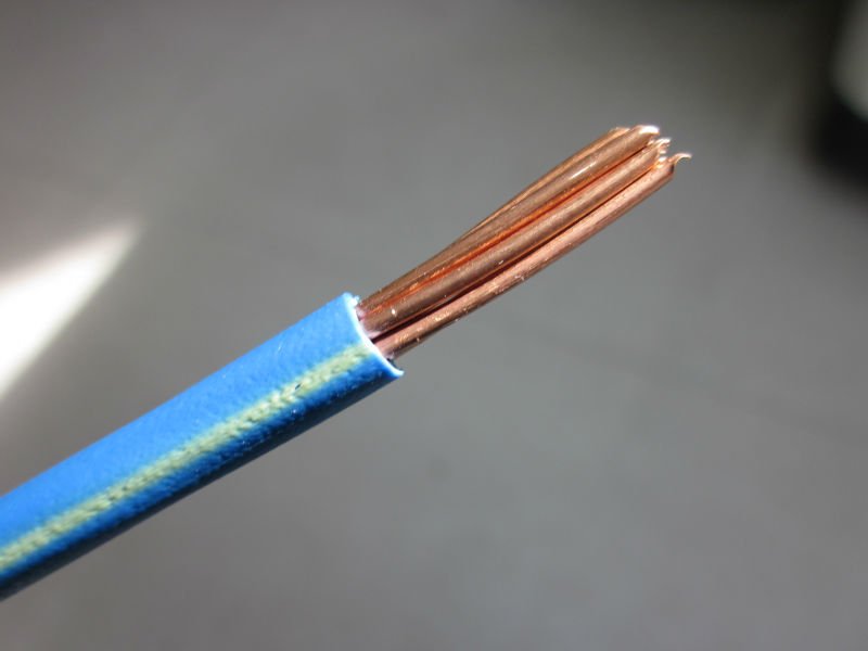
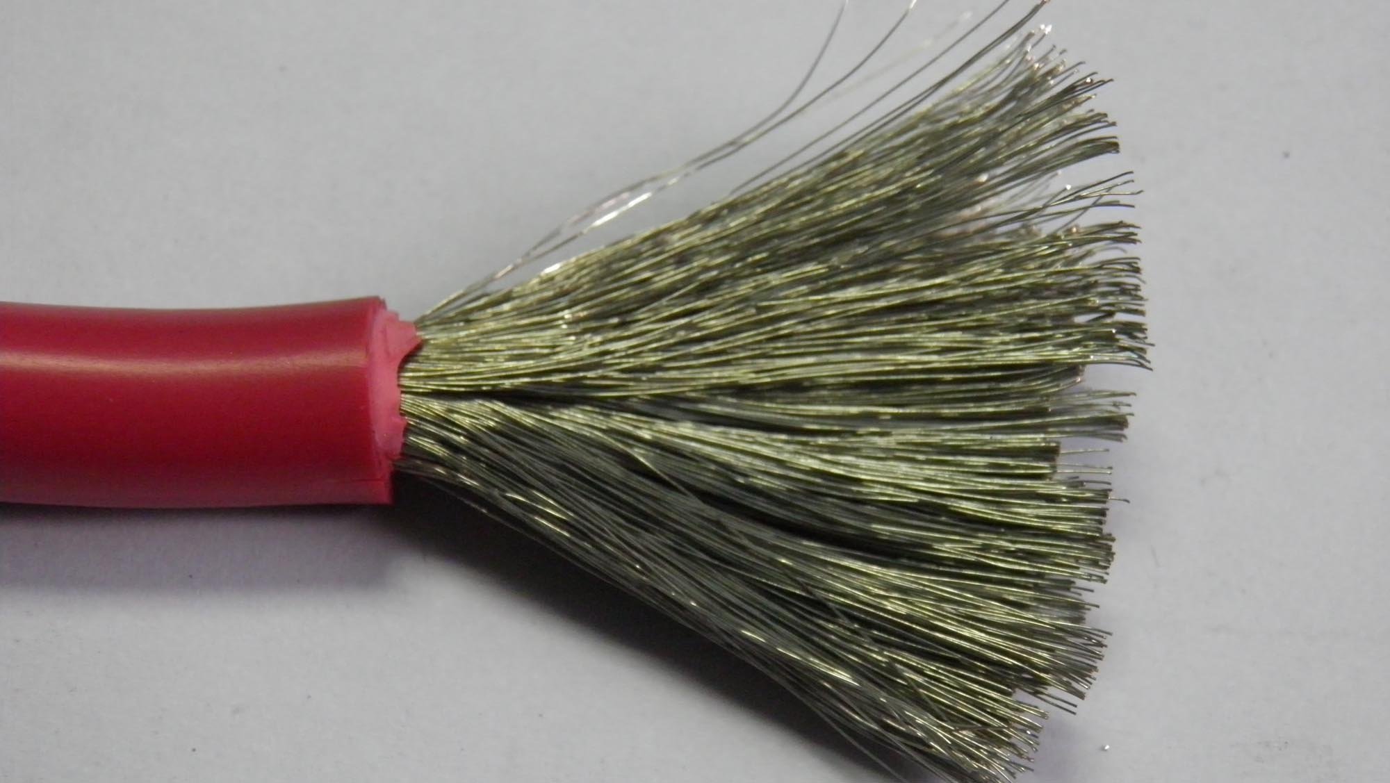
    Here are 3 examples of stranded wire.
    This type of energy travels on the exterior
    of the wire so better to have more surface
    like #3.


    #1 very course bare
    #2 Medium tinned
    #3 Very fine tinned


    Nice work Clarence, I hope good results come, Ill
    be watching.


    Last edited by BroMikey; 03-19-2016, 09:40 PM.

    Comment


    • Thanks BroMikey and Clarence for the info, hope the best for you.
      Best wish.

      Comment


      • Worked but short on amps

        Hello BroMikey,

        did not use a parallel capacitor as you can see in photos - forgot that it was already in resonance with the ZVS.

        use of a new TPC coil as a dipole worked pretty well. the first TPC coil dipole showed its usual amp draw of .54 amps with no load. nothing new there.
        the second TPC dipole with it's TBC coil energized and unloaded did not
        increase anything either. the AC voltage unloaded reading of the TBC was around its usual value of 45 vac. also. nothing new there. the rectified voltage
        from the FWBR you see in the photo was around 76 vdc. the AC output of the ZVS was 40.9 vac which was slightly different from the usual 41.70 vac.

        all of the previous values were without the FWBR placing any load on the
        whole Zvs circuit at all.

        I was not sure what the layered flux field for these FLAT Tesla coils would
        do, since it is entirely different from the vertical wound Coils that are mostly used now days. I figured it would probably have "sweet spots" that would have to be discovered by coil manipulation and that did turn out to be the case.

        I watched for two things when I made coil movements: most important was the40.9 acv output of the ZVS. any difference in it as I moved things told me whether good or bad. the second thing I watched for was the amp load on the ZVS circuit.

        to make a long story short, I wound up with 40.1 acv on the ZVS circuit
        and a value of .81 amps on the complete circuit when the rectified dcv output was applied as a load to the battery charge circuit. starting at 12.5 dcv on the battery the run time was a little shorter than the previous run times.

        the second Dipole did increase the amp value by about a half of the usual .54
        amps (.27 amps ) giving the total of the .81 amps reading.

        the main concern in all of this is that I believe the ambient background in a FLAT coil as a Dipole does not perform AMPERE wise as well as a vertical coil does! definitely not good.
        Will have to think about it for awhile to see how to improve all the new efforts.

        enjoy the photos!

        Thanks for listening!
        Respectfully,

        Clarence
        Attached Files

        Comment


        • Nicely done coil set and thanks again for the experimental
          update on what have found, step by step.

          It seems like tuning experiments will teach us all something.
          The TPC and the TBC are very interest yet different. One is
          centered on voltage? And the other amps?

          Well I thought these coils word all about getting up to a
          high voltage fast with only a few turns. There really is so much
          to evaluate with the GEGENE. The original GEGENE uses a
          higher toggling voltage on the ZVS with computer controls
          of course.

          And it seems only light bulbs were used and resistance so that
          when the high voltage hit a bank of lights all strung up in series
          the TPC that produced the dramatic increased voltage from 20vdc
          ZVS was able to produce a higher output than input.

          I was thinking that this increase in output was due to the HV
          that reduced losses because large amp flows were not present.

          The advantage is the reduced losses using HV causing the
          lights to burn very brightly, just as bright as when running
          on conventional power yet costing far less on the input.

          To accomplish the original HV a thinner wire but longer
          was used, maybe to reach 1000 volts? Not sure on that
          however it would have to be very high voltage so watch
          out for those putting that on a scope.

          Some maintain that only lights show the increase.

          Not to say that a little bit smaller voltage out put does not
          deserve just as much experimental attention as other designs
          have revealed.
          Last edited by BroMikey; 03-21-2016, 01:39 AM.

          Comment


          • Tbc

            Man experiments with TBC a.k.a. (TESLA BIFILAR COIL)
            by inducting energy from an induction cooker at 20khz

            He says he used a smaller version that operated at 140 volts
            but the one you see in this video is a little bigger operates
            at 1500 volts.

            [VIDEO]https://www.youtube.com/watch?v=5zlBsDE4rEs[/VIDEO]

            Comment


            • Hey Clarence

              Thanks for the nice foto,

              Right click on the picture and select "COPY IMAGE LOCATION"

              Tell me more.

              Comment


              • INFORMATION FOR CONSTRUCTION OF SINGLE TOROID with SINGLE CAPTOR COIL

                Originally posted by BroMikey View Post
                Hey Clarence

                Thanks for the nice foto,

                Right click on the picture and select "COPY IMAGE LOCATION"

                Tell me more.

                Hello BroMikey,

                still did not understand your CLICK AND COPY to have a photo to stay at the TOP and visible to see ABOVE all the message words?? but OH WELL -
                since you have already done it here I will go ahead and use it to the members and your advantage!!!! pull up a chair and get comfy - it's a long SOB! and eleven Photos. only six on this reply as that' all allowed on this posting - rest immediately following on another posting (Forum rules)!

                Here goes:
                1. in the schematic the Black and Blue input wires you see would be coming
                from the SMALL size CAPTOR which I have! 12KW unit (if I had the
                magnetic ground potential anomaly to enable it - which I don't have because of my location) which is the initial unit B&L used to POWER the OTHER TWO
                LARGER units. a 25KW and a 50 to 100KW unit. the 25KW unit is the one I am explaining now! onward.
                2. the first thing you see at the end of the BLACK input lead is just a normal type household circuit breaker! it is rated for ONLY HALF of the maximum
                output amperage the unit is capable of producing. they used this value
                rating so as not to OVERLOAD their unit!
                3.the next thing you see attached to the RED lead and located NEXT to the circuit breaker is a GDT( gas discharge tube)/VARACTER/LIGHTNING SURGE SUPPRESSOR. either of the three will serve the same purpose.
                4. the next thing you see is the SMALL green lead connected to the GDT/etc.
                this actually does supply HOT voltage to the LARGE GREEN GROUND WIRE
                and also serves as the POLARIZING wire for the circuit AND a NEUTRAL
                EARTH GROUND ROD SYSTEM RETURN line for the circuit - ALL at the same time. Busy! in the event of a SURGE from the EARTH - everything shuts down. NEAT!
                5. the next thing you see is the LARGE GREEN EARTH GROUND wire make a SINGLE WRAP around ONLY ONE of the (close to center turn) turns of the CAPTOR COIL. the CAPTOR COIL induces it AMPERAGE ABILITY HERE
                at this point!
                6. the next thing you see connected to the RED LEAD wire is the connection to the TOROID PRIMARY connection AND THEN ON TO SERVE AS THE CAPTOR HOT OUTPUT.
                7. the BLUE INPUT LEAD IS CONNECTED TO THE TOROID NEUTRAL wire.
                8. the next thing you will see is the CAPTOR WINDINGS. it is 7 (seven)
                feet of # 1 ought tinned stranded copper cable( from PACERGROUP ).
                it is five to six turns (closer to six) and the ends are connected by a COPPER SPLIT BOLT connector.
                the BOTTOM TURN is the ONLY one that passes THROUGH the TOROID
                CENTER ( does NOT WRAP - IF any silly so-and-so starts making WPAPS
                the WHOLE COIL will VAPORIZE! be WARNED! DO NOT DO THAT!)
                NOTE: the TORoid only uses .08 amps which will turn the CAPTOR COIL
                with ONLY that mere amps into a coil that bcan produce 1000 to 2000
                amps and you damn well won't like it! P-O-O-F!!!
                9. the CT marking near the CAPTOR COIL end connection denotes TWO
                separate pizzeo transducers (available on line) . one sends its values to a
                digital amp meter (available on line) and the other sends it values to a
                voltage meter ( available on line ).
                10. as you can see, each of the meters are powered by the BLACK and BLUE
                source leads at the top of the schematic.
                11. POINT OF INTEREST: I used a 40 watt refrigerator bulb to purposely demonstrate the minute amperage that is needed to energize the particular CAPTOR COIL UNIT. the kil-a-watt meter in the photo shows .38 amps
                for the WHOLE CIRCUIT! the 40 watt bulb uses .30 amps - that means that the TOROID only uses .08 amps to produce (in this case) 109+- amps.
                and that will NOT INCREASE no matter how much amperage the the CAPTOR COIL induces into the GROUND ROD SYSTEM!

                Now I will attach only six of the photos I made. Forum allows only that many at this time. rest will immediately follow.

                Thanks for listening!
                ENJOY!

                respectfully,

                Clarence
                Attached Files
                Last edited by clarence; 03-26-2016, 04:21 PM.

                Comment


                • More info

                  Originally posted by BroMikey View Post
                  Hey Clarence

                  Thanks for the nice foto,

                  Right click on the picture and select "COPY IMAGE LOCATION"

                  Tell me more.

                  Hello BroMikey ,

                  here's the rest of the photos.

                  Thanks,

                  Clarence
                  Attached Files

                  Comment


                  • Originally posted by clarence View Post
                    Hello BroMikey ,

                    here's the rest of the photos.

                    Thanks,

                    Clarence
                    Hello,

                    luc2010 from West Africa here!!

                    NICE PHOTOS Sir!!

                    I will give it a try and see...

                    using 500gram of copper wire 0.315 mm in diameter for the primary coil?


                    Best Regards
                    luc2010
                    luc2010

                    Comment


                    • Hi Clarence

                      I have been running around again like a chicken
                      with his head cut off and it was good o see all of
                      your hard core experimenting.

                      I will comment in time. First let me upload your pictures
                      to my website. Okay it is done. You can delete your stash
                      as it will only hold a few pictures but my tiny website
                      will handle every bodies.

                      I had promised to do that for those who have foto's
                      of their work and don't want to have to delete all
                      of their other work.

                      I forget what I got for free, it was something like
                      a couple dozen shots and if the file size was not
                      crunched down I filled my stash right away.

                      Now I just dump everything on my site so it is not
                      lost. Large of small, I have a huge area that will never
                      be used up. Then you have to do other things.

                      Never mind that just let me know when you want it done.

                      Her she is, links can be manipulated to print text in between.

                      At your service


                      Comment


                      • Hello BroMikey,

                        that's awesome with those pics doing like that ,
                        thanks as always! Clarence

                        Comment


                        • Originally posted by clarence View Post
                          Hello BroMikey,

                          that's awesome with those pics doing like that ,
                          thanks as always! Clarence

                          Hey Clarence

                          My pleasure Sir.

                          Okay I see 109 amps. That is a huge figure. I am not as
                          close to this work as you are Clarence so when I look at
                          this with a conventional mind I immediately say that this
                          circuit is very bizarre.

                          But when I look at this circuit outside the box I think that
                          YOU see what the 109 amps represents in terms of available
                          energy as you have done a Captor before other ways.

                          I assume these numbers are idling amps for the TOROID.

                          The larger awg wire circling the outer Dia. of the toroid.

                          Wow this is very different. I'll have to give this some thought.

                          Thanks for being so open share.


                          Comment


                          • I am digging around and saw I missed these also. Wow that
                            is a bunch of beautiful ART WORK.


                            You may now delete your online stash.


                            Last edited by BroMikey; 03-26-2016, 10:04 PM.

                            Comment


                            • You are one of the reasons

                              Originally posted by luc2010 View Post
                              Hello,

                              luc2010 from West Africa here!!

                              NICE PHOTOS Sir!!

                              I will give it a try and see...

                              using 500gram of copper wire 0.315 mm in diameter for the primary coil?


                              Best Regards
                              luc2010
                              luc2010
                              Hello luc2010,

                              you are one of the reasons why I put this information out there.
                              many have been asking about how to do the one toroid with the one Barbosa & Leal Captor Coil and THIS is not my setup. It is strictly the same thing they built and used and are STILL using.
                              SO be SURE to always refer back to this information and build and construct
                              every thing exactly as you see it! do NOT deviate from their method or you will screw up.

                              I am aware that you are in the process of building your own toroid with the same type of blank salvaged stator as they used. I also know that you are doing things this way because the cost and availability in your country of
                              Africa are prohibitive . my hat is off to you SIR and the many others just like you.
                              I do also hope that the location you are in is beneficial to this type of unit
                              and also to you.
                              My location did not turn out so good . However I have been working to overcome that deficiency for a good while now and will continue to do so.

                              I will always wish the VERY BEST to you!!!! keep doing the good things and it will happen!

                              thanks for you comments!

                              Respectfully,

                              Clarence
                              Last edited by clarence; 03-26-2016, 10:04 PM.

                              Comment


                              • Toroid amps always are the same

                                Originally posted by BroMikey View Post

                                Hey Clarence

                                My pleasure Sir.

                                Okay I see 109 amps. That is a huge figure. I am not as
                                close to this work as you are Clarence so when I look at
                                this with a conventional mind I immediately say that this
                                circuit is very bizarre.

                                But when I look at this circuit outside the box I think that
                                YOU see what the 109 amps represents in terms of available
                                energy as you have done a Captor before other ways.

                                I assume these numbers are idling amps for the TOROID.

                                The larger awg wire circling the outer Dia. of the toroid.

                                Wow this is very different. I'll have to give this some thought.

                                Thanks for being so open share.


                                HelloBroMikey,

                                with respect to the toroid amperage BOTH of my toroids TOGETHER are ALWAYS at idle and only consume .08 to .3+- amps ( the variation
                                depending upon whether or not they are in or out of saturation - and they do that off and on continually while in use) . they NEVER go over that amount
                                regardless of whatever the rest of the unit is doing. never.

                                once they start doing their job they are CONTENT to just sit there forever
                                as if they were on vacation. that I have always liked about them.
                                small but powerful!
                                ALSO BRO. the reason I was so adamant about making only ONE WRAP around the blank part of the toroid is because I tried making my usual 2 1/2 wraps
                                as I did on my unit and when I eventually turned the unit on with my AMP meter clamped in place the amperage on the clamp meter immediately went to 280 AMPS!
                                and the cable went HOT BIGTIME ALSO!!!!! so I shut it off and re worked the cable through the center of the toroid !
                                So if you think 109 + amps is HUGH think again, and still only at .o8 amp to the toroid!

                                thanks again for listening!

                                respectfully,

                                Clarence
                                Last edited by clarence; 03-26-2016, 11:20 PM.

                                Comment

                                Working...
                                X