 Tweet
Tweet
For those who are interested some preliminary info.
Although we have had some delays (together about 2-3 months) I still believe I can publish the complete diagram, workings and mapping to Tesla's writings before the end of this year.
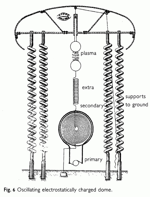
The document in the link describes the three coil Tesla transformer as I have built it.
At half power it produced a spectacular display of streamers.... and blew the primary capacitors.

So it requires some repairs now.
Still some work has to be done to make it a TMT.
More on that later...
Any comments on the document are welcome.
more on this project can be found here.

Ernst.
Although we have had some delays (together about 2-3 months) I still believe I can publish the complete diagram, workings and mapping to Tesla's writings before the end of this year.
The document in the link describes the three coil Tesla transformer as I have built it.
At half power it produced a spectacular display of streamers.... and blew the primary capacitors.
So it requires some repairs now.
Still some work has to be done to make it a TMT.
More on that later...
Any comments on the document are welcome.
more on this project can be found here.
Ernst.
") )
)


 This is how they 'promote' Tesla's legacy!
 In fact that every picture makes things complicate unnecessarily


Comment