Rake and Shunts...
Hello to All,
@Mikey, the Rake is as Mario said, an inclination of the ramp. The Angle of adjustment.
Shunt is a deviation: "push or pull (a train or part of a train) from the main line to a siding or from one track to another..."
In this case the Bedini's iron ramp creates a "shunt" by attraction to the approaching North Pole from Rotor.
I am certain the "Key" here is to start by having a perfectly balanced system, just between magnets (not including ramps)...Now, the Gap is also important...since we may obtain a great balance BUT with too wide gaps...which is definitively not good! (we are cheating...lol) . Meaning, the Two opposite Forces (Repulse-Attract) MUST be there (Exist) AND with a lot of strength...except they are cancelling out in a straight vector at 180º. However, both forces are there.
The point to understand here is that cancellation of forces ONLY take place EXACTLY in the 180º ALIGNMENT LINE between Rotor-Stators for EACH Module...so, after that particular line-point, they are no longer cancelled, meaning they are there in FULL STRENGTH EACH...to interact with ramps...
I also believe the acceleration Ramps which generates the "Positive Unbalance" to our Balanced System should be equalized as well, in order that those unbalancing forces are distributed equally across the 180º. This way two acceleration vectors of the same magnitude would take place at each Module of Two Rotors and Two Stators.
I see many possibilities of designing the ramps shape for each module...and not necessarily ramps need to be "Symmetrical" or identical, since we are dealing with two different type of forces....but, only testing each one would give us the better ones.
Regards
Ufopolitics
-
In Bedini's drawing the the shunt is the part of the ramp where the iron connects part of one pole to the other pole of the stator magnet.
Rake means inclination.
MarioLeave a comment:
-
Originally posted by Turion View Post
Wow that is a statement that had not sunk in yet I didn't get
that til now, well i don't know what a shunt is yet either.
Thanks - A -Million Dave, right when i needed to hear more, I'll give
it top priority. Here is my progress report.
Below is FIG.A and FIG.B they show the influence that a single ramp
has on the repulsion side using a thin piece of PC power supply metal
1.25" wide @ approx 6" long. I see that my magnets are weak when
it come to induction forces so it became imperative to arc some of the
ramp to keep a .120" gap all long the travel area between rotor and
that half of the ramp. The angle plays an important role in induced
field strength that effects the distance the rotor travels.

No where in the Bedini diagram is there a mention of a shunt.
Also Mack talks about "rake of the ramp" and i don't understand
those terms or what they mean.
here it is again.
 Last edited by BroMikey; 09-09-2015, 09:09 AM.
Leave a comment:
-
When faced with an issue, go back to what Mack said:
"What is needed is less magnetic drag than the torque the ramps can provide. Anyway, get the neutral balance first.
A shunt on the repelling stator magnet similar to the Bedini drawing will kill some of this neutralization and add to the torque. You only need the neutralizing action of the repelling magnets after they pass their center lines. Any neutralizing affect you can eliminate before that point is beneficial. Likewise reducing back drag attraction on the attracting set, with a shunt on the other side of this magnet from its ramp, can also benefit. I can not provide details on the shape of the shunts or any spacings they may have. Look at the Bedini picture for ideas. Too big of a shunt will make things worse."
DaveLeave a comment:
-
This is what I found out by trial and error here in this diagram.
The dimensions are not perfect on the ramp yet. What happens
is that the entire length of ramp attracts the rotor magnet except
for a tiny portion right up where the ramp sits next to the stator
magnet.
This is the repulsion side and as always the repulsion area on both sides
of the magnets center has an ever increasing or diminishing amount of force
on either side of the maximum center of the repulsive forces.
I had the rotor spinning tonight very freely with the new stator
mounts working perfectly. Then I accidentally bumped the rotor
magnet and it cracked, dug it out and reglued a new one in about
4 hours ago.
Also I am putting a white dot on the rotor magnets closest to the
stator magnets and a dot on the stator magnet where the center
of the forces are at there strongest point.
This way makes it much easier to find the optimum cancellation
position.
I also found out by experimentation, just as has been pointed out, that
the repulsion side gap between rotor and stator magnet must be set
closer together to increase the field strength in order to keep up
with the attraction side. So the attraction side must be a tiny bit
stronger as evidenced by the need to close the gap on the repuslion
side to acquire more field lines.
It is a very small difference but none the less.
Happy experimenting
 Last edited by BroMikey; 09-09-2015, 04:29 AM.
Leave a comment:
-
Hi UFO, I think your right , I went back and redid my test.
I was bringing a magnet towards a piece of rectangular steel, that had the opposite pole magnet on it at one end. When the rotor magnet was close enough( to the opposite end) the piece of steel moved away.
But with a longer length of steel , it didn't happen until it got close enough to the attached magnet.
Not trying to misinform ,just trying to explain what I see.
I still think it will balance without something changing.
Sorry about that folks.
artvLeave a comment:
-
Okay I have realized something very important tonight. I have
been unsure of the direction of rotation and have changed my
rotation direction 3 times. First time after Dave's video I figured
maybe he was going in the right direction but wasn't real sure
because no ramp is shown yet for the first stage. But, when
UFO posted all of his awesome design graphics, I had to wonder
if his rotation direction was right or was Dave's video right.
I didn't know which way to go at first till I looked at the effect
the ramps have that will come later.
It is starting to make more sense now Mack, why you pointed out
that I needed to be more sure which direction was right for my build.
My magnets are angled opposite the UFO drawing.
What I see clear now is that which ever way we angle the magnets
the leading edge should be the side that is the weakest as it makes
it's approach toward the ramps first and then afterward the closest
portion of the rotor magnet to follow.
Maybe I am not able to explain this to others very well but I see it
clearly now.
I just makes the most sense to have the rotor magnets weak side
to induce a field into the ramp first instead of the other way around.

Leave a comment:
-
Hi StealthOriginally posted by Stealth View Post
There are a lot of things we can all share with one another such
as our practical experiences for material handling. Many do not have
the one thing or they have the other thing and they get stuck so
it is good to make up for one's weakness by giving practical application.
It is easier said than done. Good to see you are going to keep an eye
on this new thread. I couldn't think of any better material this time
for a one shot deal where a test or two will be the end of this machine
except for demonstration purposes, so I chose wood. And wow wee that
8X locktite Pro series is the kitty cats meow when it comes to bonding
to just about anything.
For those of you who want a good solid piece of wood that doesn't
cost you one hundred dollars go to your local furniture/appliance dealer
where a steady stream of cast away master bed head boards are
thrown out to the rain and snow.")
I have enclosed an updated diagram that is showing my stator magnet
assembly for anyone who wants their way paved.
Look to the left of the diagram for the stator magnet mount.
The hole is made
oversize with a large flat fender washer that is 2" away from the magnet.
I might change that to a SS washer but maybe being 2" away won't
throw it off. This arrangement can be snugged up with the 1/4-20 ss bolt
and still be moved with a good strong hand in all directions.
As soon as I get what I want (The first Stage) I will show this in a video.
The next step will of course be to redirect the the machines balanced
lines of force to make it run all by it's lonesome. Well not quite til I
add a few more sets.
 Last edited by BroMikey; 09-08-2015, 09:03 AM.
Leave a comment:
-
If some of you guys are having trouble finding suitable material to build a rotor and or stator out of, there is an available solution. You can purchase a nylon or plastic disk used for cutting boards. They come in different shapes from round to square to rectangular. And they are not that expensive. Good Luck. stealthLeave a comment:
-
Originally posted by boguslaw View Post
Hey Bog..........
I am all ears but the problem is sometimes your English makes no sense.
UFO has shown how the design does work and that it is more than a toy
so go ahead with your magnet motor theory. What college? After all of
years of speculating what your thoughts might be, I guess we can
wait a few more decades?
Either way it has become very clear time and time again that the
models for just about every principle taught in schools are inaccurate.
As shown in post #167 as Randy has pointed out, UFO's run down of
the obvious facts in the experiment takes presidence.
Presidence meaning, taking first place and does supersede the dern
dogma force fed the yuppies looking only for the money trail.
On the other hand their are those of us who have "had it" "UP THE HERE"
with following the phony leadership who have been shown to be unable
to find their heads with both hands on a good day.
We have done our bid for THEIR version of GOD and Country. To break
free from the systems clutches we must do the investigation first hand.
As UFO has shown in pictures, just like Howard Johnson tried to do, the
bloch wall moves and many other advanced interactions take place.
Most of what Howard J. has shown is not excepted by mainstream
science, only the portions of his work that compliment mainstream
philosophy/dogma/deadends.
Always with just a "HINT" that it might work. Or that nobody knows
for sure. The facts have been in for years. Some of the first powerful
magnet motors were bought up in the 1950's with their inventors
having long since expired. These inventors were silenced with money
and or threats til such time as their passing would cause their inventions
to be "out of sight out of mind".
Think about it.
Great going to all of the guys for holding the investigation data above
the dogma/peer pressure driven robots with their intimadating
non-sense.
Yours Truly
Leave a comment:
-
Stator Magnets
Hi Grum,Originally posted by Grumage View Post
Yes, the stators are easily adjusted, but I believe the rotor angle is going to be what is adjusted to maximize the torque from the ramps. To me, the stator angle will be what helps with the transition from the ramps since we know the strongest flux extends from the edge of the magnet, not the center, and the ramps on the repulsive side is going to be out of balance from the attraction side. If you use symmetrical geometry that is. I see the addition of the ramps as unbalancing the system and I think Mack may have already said that somewhere. I see a possible sticky point between the repulsing stator and the ramp leading to it. A challenge, for sure. But what do I know.
Thanks Ufo for the iron attraction info. I was wondering if anyone had actually measured the pull between the two scenarios. It makes sense that the added energies of biasing the iron would increase the pull. Don't prosecute me for just calling magnetism energy. Its just easier that way.
Take Care,
RandyLast edited by tachyoncatcher; 09-07-2015, 05:22 PM.Leave a comment:
-
Randy,Originally posted by tachyoncatcher View Post
The answer to your (apparent) simple question, according to my experience is not simple.
When you approach two magnets by their opposite poles, those two poles making contact actually disappear (effect that Ken Wheeler calls "Voidance"), and what was each magnets dielectric center plane at each... actually disappear to 'merge' right at the seal between both poles surfaces.
[IMG]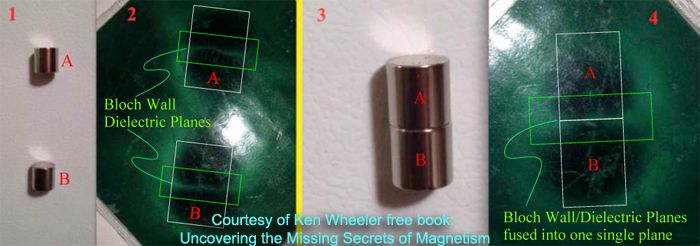 [/IMG]
If you "sandwich" a piece of iron between the same kind of approach, the dielectric plane merges right in the center of iron piece. So the iron serves as the bonding mass between both magnets.
Getting to your question:
1- When you approach a magnet to plain iron, that contacting pole just starts taking over the whole piece of iron. By logical deduction that contacting pole weakens related to the opposite one since it is expanding to a bigger volume mass.
2- But, if you approach Magnet to an Influenced Iron by the opposite pole, it is a stronger reaction than previous example (1) just because is bonded by two attracting vectors, plus the other two exterior poles are also interacting by displacement of the Dielectric Plane.
This reality applies exactly the same way by making contact...or merely approaching by an air gap.
Anyways, that is my opinion...it may differ to other Members criteria...
Regards
UfopoliticsLast edited by Ufopolitics; 09-07-2015, 05:10 PM.Leave a comment:
-
Another Question
Which is stronger, or is there a difference between the attraction forces of a magnet and iron. Versus the same magnet/pole and the same iron biased with a attracting (opposite) pole? I really don't know nor do I have the scales to test this.
Thanks,
RandyLeave a comment:
-
Sweet
Thanks everyone! I will be using a variant of Ken's idea with some aluminum angle I have. I know, I know, eddy currents. Not perfect but maybe good enough. I do not have plastics or the machining tools for plastic/metal, only wood working tools. And lots of glue. I want to be able to adjust the angle 30-45 degrees as suggested. This will skew the center line unless I get things exact. As Mack said, easy to fail.
Ufo's post #167 above is dead-nuts-on. Easy to test yourself. I did. I still think we will have to further scrutinize the interaction between the ramp being induced by a north rotor and the south stator. This is probably where shunts will be required.
Thanks Again,
RandyLast edited by tachyoncatcher; 09-07-2015, 03:59 PM.Leave a comment:
-
Originally posted by Turion View Post
I agree to above Turion, it is just like a Two Pole conventional Motor will work same as a Four Pole...except more torque/speed on the later.
UfopoliticsLeave a comment:

Leave a comment: