 Tweet
Tweet
-
-
http://www.free-energy.ws/pdf/magneteal_industries.pdf
https://documents.pub/reader/full/bo...on-user-manual
Magnipulsion engine. Soon to be ruling the world. Another false promise.
 Last edited by BroMikey; 02-24-2022, 07:21 PM.
Comment
-
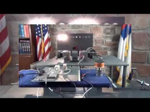
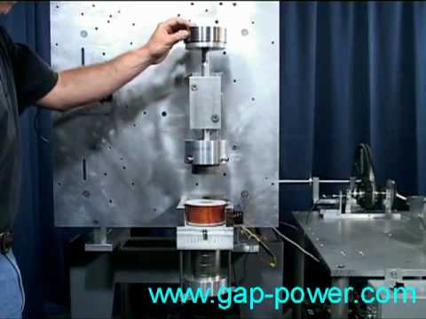
Gap power update 2015
Comment
-
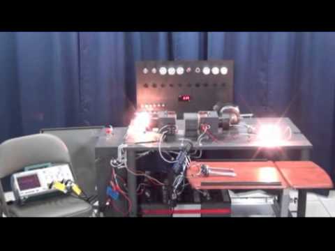
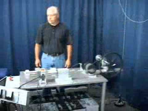
90% of the electrical current from the battery is returned in this V8 solenoid engine

Comment
-
That's stupid. 100% of the "electrical current from the battery is returned" to every battery all the time. Fact.Originally posted by BroMikey View Post
bi
Comment
-
You misunderstood. With the correct circuits 90% of the convention motor design can be recovered. Regular induction motors can not collect a dc collapsing field so easy.Originally posted by bistander View Post
It's not nice to say stupid in all your posts. You are a very evil person, full of puss and sick venom . Induction motor design is outdated like you grandpa
Induction motors are not pulse dc engines.
I can feel the unclean spirits pouring off of your toxic comments and feel dirty afterward.
 Last edited by BroMikey; 02-25-2022, 04:43 PM.
Comment
-
More on motor recovery electricity. Both drive battery and bemf collection battery charge while the motor gives up free mechanical/ kinetic
Battery Pair Switching Demonstration 2 - Benitez and Bedini Combined
 Last edited by BroMikey; 02-25-2022, 12:43 AM.
Comment
-
Discussion of Lenz on one of the forums:
That is an awful long time of 6.2 milliseconds for a DC switch to close, and for the magnetic and electrical field to "build" in a line.
In my pulse motors, the pulse is usually 1 or 2ms...
A full half-wave of a 60hz sinewave is 8.3ms...(!)
I would assume after that 6.2ms is when it becomes saturated sort of, and now the third inherent component of electrical flow; heat, appears.
Also will assume the electrical flow of electrons comes first, then followed by the magnetic field.
And when Tesla says "to build", that means the magnetic field finally becomes strong enough to do some work, like pull a piece of iron or push a magnet
Anyways if so, this makes it very clear and believable how you can make a rotor of permanent magnets lets say 16 of then NSNSNSNSNSNSNSNS and whip them around past a coil, then load the coil or short it out, and the loading does not cause lenz law braking, instead speeds up rotor under loading.....
as if it takes 6.2 milliseconds for magnetic field to build when a DC switch closes, then you would assume a similar time of 6.2ms it takes for the lenz braking effect caused from backemf forces of the loaded coil to manifest with enough force to pull that rotor magnets backwards against rotation.
If so, then the RPMS of those 16NS rotor magnets in a rotor against the loaded coil can be adjusted to be just the right "window" of RPMS to be where the upcoming "trailing" magnet is what gets hit by the backemf lenz forces, not the magnet that just induced the loaded coil in first place to be creating the backemf forces that are "supposed" to pull the rotor magnets backwards against rotation braking it.
So instead the upcoming "next magnet in rotation" gets hit with the backemf forces....and if that is of reverse polarity to the "leading" magnet then its going to push or pull that rotor forward in rotation, speeding it up. Seems like all it takes is simple mathematical calculation of the time between magnets at certain RPM (or magnet edges) to figure out just how fast to rotate the rotor.
I see how with a coil, both the speed of travel and the magnetic field manifestation would decide the time that lenz law braking forces would come into force. But ball park it should be around that 6.2milliseconds I bet.
Impedance of loaded coil also factor as a 100ohm coil is going to take longer for a strong backemf magnetic field to develop than a 10 ohm coil....
�Advances are made by answering questions. Discoveries are made by questioning answers.�
�Bernhard Haisch, AstrophysicistComment
-
I thought I posted these results here, but possibly not.
Testing of three different individual coils.
Iron core 35 v @ .4 amps
A pair of these coils produced .8 amps at 96 volts across the load. I am having a hard time understanding why the same pair produces 130-140 volts across the load at 1.5 -1.9 amps on the older machine. The only difference is 12 magnets on the old rotor rather than 24. Same size rotor. Same RPM. Same strength of magnets.
New permalloy core 33 v @ .4 amps
A pair produces about the SAME as a pair of iron core coils, but without the heat.
Extended permalloy core 14 v @ .25 amps. Still working on trying to get it to go farther in. Lots to do and no time to do it. Trying to understand the different results on the two different machines.�Advances are made by answering questions. Discoveries are made by questioning answers.�
�Bernhard Haisch, AstrophysicistComment
-
It is good to hear you are thinking about this problem. I may not be easy to solve. Our spewing nemesis is trying to disrupt the continuity of a kindly exchange with the goal of poisoning my thread. He goes after the stink of it all (spookie dookie) and must be eliminated.
Anyway I'll finish him later.
The obvious choice for you is to try shorter coils because the longer coil impedance is so great at those frequencies that power (assuming the gap is 1mm) has dropped. You are now in the same general zone as Thane, as he runs 1500hz. Now why have I brought this up? The reason is clear, Thane was struggling to find a coil that produces a good amount of power and has used a shorter coil. He use to use those big balls of wire like you use but explained that he could not get the amps.
Try 500 ft and put them all in parallel. This will dramatically change the impedance. You are not running 1500hz like Thane, you are running a little lower (1100hz)
Earlier this week you mentioned that you needed to rewind the 12 strand coil? You must have lost all of your old coils or they don't fit the new machine. Or pull 12 magnets on each bank or set the gap to under 3/16"
Originally posted by Turion View PostNot to be trusted. Bye is poison.Originally posted by bistander View Post
Comment
-
-
Here is a video on magnetic neutralization, free lectric to boot
Comment
-
Comment
-
bro,
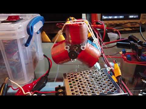
All my coils are wound with #23 AWG. All have as close to 3,000 feet of wire on them as I can get in different configurations.
All my coils are wound on a bobbin (except the single extended core coil) that has a 3 1/2" flange. A 3/4 arbor hole. A traverse Length of 3" and a 1" barrel.
http://www.norticinc.com/plastic-spool/
Currently I have 12 coils that have iron cores. These are from my old clunker machine and are the "version" of the coils I have used for YEARS. I have gone through several sets of these coils because when run too long, the insulation will melt off and the windings will short out. Which is why I have been searching for a new core material.
They are all wound with 12 strands (so 250 feet each) and each have four strands connected in series. Which means 3 wires coming off the coil, each with four strands of 250 feet connected in series to equal 3,000 feet of wire on the coil.
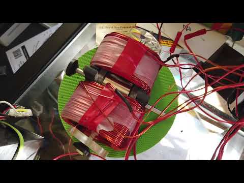
I have 12 coils with the permalloy cores. They each have 3 strands of 1,000 feet in parallel
I have 1 coil with a 4" traverse length that has a permalloy core. This is my extended coil that is producing so little. It is wound with 3 strands @ 1,300 feet each.
My guys in Sacramento have several test coils wound with different wire lengths that add up to 3,000 feet of wire on the coil. The all have the permalloy core. THESE WERE THE COILS WE TESTED
1 coil with 3 strands of 1,000 feet
1 coil with six strands of 500 feet (groups of two in series so that 3 wires come off the coil)
1 coil with 12 strands of 250 feet (groups of four in series so that 3 wires come off the coil)
1 coil with 24 strands of 125 feet. (groups of 8 in series so that 3 wires come off the coil)
Of these coils the one with six strands of 500 feet, with groups of two put in series, produced the most power. But NOT that much more than a simple three strand coil, which is much less work.
Between now and next Saturday I am cleaning up my shop and getting things organized. Next Saturday the guys from Sacramento are coming out, bringing the old clunker machine, and helping me set it up. We are going to run the coils we have on both the old clunker and the new machine to compare results so we can make some decisions.
Of note: Today I ran the machine with two of the New coils that have the permalloy cores and three strands of 1,000 feet on them. On the OLD machine this exact same coil would cause speed up under load of the prime mover and decreased amp draw at 2840 RPM. I was thinking that number was 2800, but that was for the iron core coil with 3 strands of 1,000 ft. So I went the wrong direction with my testing.
I reduced the input voltage and measured at 2750 RPM, 2700, 2650, etc. all the way down to 500 RPM, and was unable to achieve speed up under load at ANY RPM. So tomorrow I will start at 2800 and raise the rpm to see what the results are going in that direction. Hopefully I will figure it out.
Note: "Coil span overlays pole pitch" do not apply to figuring out the output of generator coils on my (LOL) "4 pole machine". (I did not realize that a machine with 24 magnets on the rotor had 4 poles per coil. You learn something new every day.) You would expect that someone who understands my machine SO WELL that they are able to evaluate how well it works would know how many poles it has, wouldn't you? And how would you even figure coil span in THIS machine?
If you want to know what these terms mean and what they DO apply to... https://www.youtube.com/watch?v=HjlxcKXOR78
It is my understanding that the DESIGN factors that determine the output of the coil are number of turns, strength of the magnetic field and rotational speed of the rotor. All other factors of note would impact one of these three. For example, core material choice or diameter (In this particular design) affects magnetic field strength.Last edited by Turion; 02-26-2022, 06:15 AM.�Advances are made by answering questions. Discoveries are made by questioning answers.�
�Bernhard Haisch, AstrophysicistComment
Comment