If this is your first visit, be sure to
check out the FAQ by clicking the
link above. You may have to register
before you can post: click the register link above to proceed. To start viewing messages,
select the forum that you want to visit from the selection below.
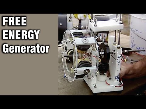
No flywheel just a modified generator that is zero cog lenz free that took a person their entire life to design. This is how it's done with all of the so called magic units with flywheels. They all modify the generator just like Thane Heins has done only in a different way. No laws of physics broken just follow the music, if you try you will succeed.
Edit:
in the down time I have been testing the coil output with rotors on BOTH ends of the coil. The output is DIFFERENT, as are the operating electronics. If I ever build another setup, it will be….
Plate with adjustable opposition magnets - rotor - six coils - rotor six coils - rotor - plate with opposition magnets. It can be run as just a generator or as a motor and generator at the same time. If run as motor and generator at the same time, you don’t need the opposition magnets, so that’s probably the best use of resources.
Edit:
......I have been testing the coil output with rotors on BOTH ends of the coil. The output is DIFFERENT......
If I ever build another setup, it will be….......
......run as motor and generator at the same time, you don’t need the opposition magnets,
It sure is nice to gawk at such a pretty piece of plastic. Isn't that amazing what money can buy? I'm jealous. That is the most precision rotor and box you have had yet. This new guy did you right.
What is the output per coil of the dually? 100w , 200w or haven't you got that far yet?
How can you do away with all those extra magnets? huh?
The previous rotor was 1 3/4" thick. We drilled a 5/8 hole all the way through the rotor. Then on each side of the rotor we widened that hole to 3/4" diameter, but only drilled the new holes 3/4" deep. That left a 1/4" thick piece of plastic in the middle that only had a 5/8" diameter hole drilled in it. A 5/8 x 1/4" magnet was placed in this smaller hole and a 3/4 x 3/4" magnet was put on each side of it. All three magnets were magnetically connected to each other, so none could be easily removed from the rotor, and they certainly didn't come out just from spinning it. To remove one of the 3/4 by 3/4 magnets, you have to break its bond with the 5/8" magnet, which could easily be pulled out of its hole, except that it is attached to the other 3/4" diameter magnet on the OTHER side that you can't pull through the 5/8 hole.
The new rotor has a single 1" x 1" magnet in a 1" thick rotor. Magnets are glued in, and held in place by a set screw. Far fewer magnets. 1/3 to be exact. But 1" x 1" instead of 3/4 x 3/4. Not as secure as the other method, but since the magnet will be attracted to cores on BOTH sides of it, I am hoping it will remain in place and not come out.
I tested several 4 magnet rotors.
3/4" x 3/4" magnets I have been using output 14.9 volts at .00 amps
1" x 1" magnets output 50.3 volt at .015 amps. These are the magnets I will have on my NEW rotor.
2" x 1/4" magnets output 50.3 volts at .01 amps to the load. These were the ORIGINAL magnets that (with six of them on the machine) at the correct RPM, output 130 volts at .75 amps, and this is what my understanding of what is possible have been based on. I had no idea that changing to a different size magnet, even though I had FOUR TIMES AS MANY would so drastically decrease my output.
Just the new rotor and the modifications to the old box for bearings and everything was like $1,600.00 Luckily I am working with some folks who paid for it so I didn't have to.
I haven't looked at the output of the dual rotor machine with anything except ONE coil. I used one of the coils from my generator and two rotors with 4 magnets in them that were 1" x 1" so I could compare to the SINGLE rotor with four 1" magnets (from the test above). I did not get 200% with two rotors, compared to one rotor, but I got enough, and when you FIRE the coil as a motor coil with rotors on both ends of the coil, that's a whole new ball game. That compressed magnetic field from magnets (rotors) on both ends of the coil is a dream come true. I will NEVER build another single rotor machine as long as I live. Never. NOT EVER.
The previous rotor was 1 3/4" thick. We drilled a 5/8 hole all the way through the rotor. Then on each side of the rotor we widened that hole to 3/4" diameter, but only drilled the new holes 3/4" deep. That left a 1/4" thick piece of plastic in the middle that only had a 5/8" diameter hole drilled in it. A 5/8 x 1/4" magnet was placed in this smaller hole and a 3/4 x 3/4" magnet was put on each side of it. All three magnets were magnetically connected to each other, so none could be easily removed from the rotor, and they certainly didn't come out just from spinning it. To remove one of the 3/4 by 3/4 magnets, you have to break its bond with the 5/8" magnet, which could easily be pulled out of its hole, except that it is attached to the other 3/4" diameter magnet on the OTHER side that you can't pull through the 5/8 hole.
I did not get 200% with two rotors, compared to one rotor, but I got enough, and when you FIRE the coil as a motor coil with rotors on both ends of the coil, that's a whole new ball game.
That compressed magnetic field from magnets (rotors) on both ends of the coil is a dream come true.
Fire from two sides on motor coils. Ding, you hear hear that bell ringing?
The new rotor has a single 1" x 1" magnet in a 1" thick rotor. Magnets are glued in, and held in place by a set screw.
Just the new rotor and the modifications to the old box for bearings and everything was like $1,600.00 Luckily I am working with some folks who paid for it so I didn't have to.
Still cheaper than the space shuttle landing. like this?
The primary electromagnetic field energy can be used a second time, after it has been used to create the desired (motor action, motive force)/change in kinetic energy of the secondary magnetic field being acted upon when it is allowed to collapse back into an electric storage container such as a battery as it would do naturally if permitted to once the input current is removed.
The ReGenX Generator Coil is an improvement whereby the conventional generator armature reaction which produces a counter electromotive torque is reversed and produces a complementary electromotive torque in its place.
I tried using the “C” core coils with a single rotor and it DOES work, perfectly, and produces far more power than standard coils with a single rotor, but I went away from that for a couple reasons.
First, those “C” coils are difficult to wind.
Second, I was limited on the size of the coil by the size of the “C” core I could find.
Third, it left no place for opposition magnets.
Fourth, custom “C” cores are very expensive…far more expensive than simply adding a second rotor.
A dual rotor machine gets you ALL the advantages of the “C” core but allows you to use standard coil bobbins and inexpensive cores. You also have a place for opposition magnets to go if you need them, or 12 more coils ( six on each end) if you don’t. That is why Bob and I are building such a dual rotor machine. Rotors are done and Bob picked them up last week. Working on Black Beauty while I wait for them.
As far as I can tell, the only advantage of the “C” core is economy of space/ size. That may be important to Thane, who is trying to power a motorcycle with a small device, but for proof of concept or to just build a machine that works I would recommend the simple choice of dual rotors.
To be clear, the only “C” cores I have experimented with were made out of a specific volume of shotgun shot mixed with epoxy and poured into a mold. I used the same material as the cores for a standard coil bobbin. This allowed me to compare the outputs between a single rotor and a standard core and a single rotor and a “C” core. No comparison, which is why Thane gets more power out of HIS coils than I do out of mine.
I also made toroids using this same process because it allowed me to make them whatever size I wanted. A note to anyone who wants to try that process…when pouring a “C” core or a toroid, I would first mix the shot and epoxy and pack it into the mold, which sat on a piece of cling wrap. Once it had hardened, I wold pull the mold up about 1/8 of an inch and then fill it with just epoxy. When that was dry I would flip it over and repeat that process on the other side. Without that solid layer of epoxy on both sides, the “C” core and the toroid were too fragile. So definitely a 3 step process if you want it to work correctly.
I tried using the “C” core coils with a single rotor and it DOES work, perfectly, and produces far more power than standard coils with a single rotor, but I went away from that for a couple reasons.
First, those “C” coils are difficult to wind.
Second, I was limited on the size of the coil by the size of the “C” core I could find.
trying to power a motorcycle with a small device, but for proof of concept or to just build a machine that works
To be clear, the only “C” cores I have experimented with were made out of a specific volume of shotgun shot mixed with epoxy and poured into a mold.
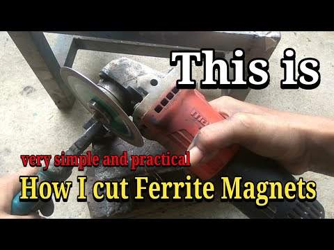
Thanks for sharing all of your work on cores made with bb's. Anyone wanting to wind inexpensive ribbon for cores as well as ferrite, they can be cut in this way. Or use a wet saw for cutting ceramic tile works or put one of these blades on a chop/miter saw. Please clamp ribbon cores which are not sintered for best results. Of course this method is not good for cutting bb's
 Tweet
Tweet
 That is the most precision rotor and box you have had yet. This new guy did you right.


 like this?


Comment