555 timer and this $2.50 book. Priceless
https://www.amazon.com/Ultimate-Begi...s%2C343&sr=8-4
-
Good job study the video. The video is only 1 piece of this puzzle. The video teaches us how to pulse DC to a motor and recovery 85% of that energy back to a battery. That is a big deal.
Let me repeat- the video teaches us some history on how to run a motor more efficiently than regular engines can.
Motors, engines, whatever you want to call it
I will say it again like this, the video teaches us all to run an electrical motor for 85% cheaper.
Think of it like this, we know from the books 1hp=750watts and regular motor are only 80% efficient or they loose 20% of 750watts so a 1 hp electrical motor uses 600watts and looses 150watts.
The video teaches us that the same 1hp motor uses 600watts but does not waste but instead recover 85% of the 600watts which = 510watts returns. So a 1 hp motor only takes 90watts instead of 600watts.
That is a big deal.
Now to answer your question you may gain 10% by pulsing the DC but that flywheel should give you 200%
https://www.amazon.com/RioRand-7-80V...%2C156&sr=8-14- Control power: 12V within 300W ; 24V within 400W ; 48V within 450W ; 72V within 500W
- Duty cycle adjustable range: about 1% -100%
- PWM frequency: 12KHZ
Last edited by BroMikey; 05-23-2022, 02:14 AM.Leave a comment:
-
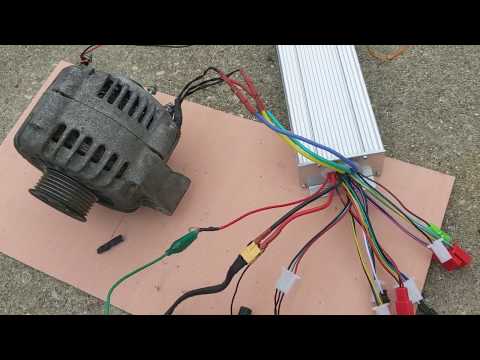
Dear mikey, the system already works, because the alternator disassembled in the picture gives me the necessary current, and the system runs because there is a 24v brush-less direct current motor mounted on the side on the right that makes the whole rotate . The problem is that the engine absorbs more than the alternator produces (in fact there are batteries connected), so I wanted a circuit that would allow me to power this engine with pulses, and therefore look for the best combination of the length of impulse, to see if it is possible in this way to produce more than what is consumed. Thank you for the video, I was already watching it on youtube, but being long enough and in English, for me, as an Italian, it takes time to understand it, but I'm trying to complete it to understand its explanation, thanks always for your kindness and availability.Leave a comment:
-
Motor windings need a sinewave. Using pulsed DC this Chinese scooter controller does this. Memphis you don't have a 3 phase motor with hall. You don't have a DC motor of a conventional design either....
You must have a target speed. Current is controller like this........
THE first step for you is to add a small timing wheel to the shaft with tiny magnets. I used an aluminum hub for $5 plus some 1/4 thick plastic disc about 3" DIa.
your design will never self start, you will need to push it by hand in the direction you desire.
 Last edited by BroMikey; 05-21-2022, 10:35 PM.
Leave a comment:
-
but my problem is not the alternator that works very well, but I just need a circuit that sends me the current to the 24v brushless direct current motor that pulses the flywheel, therefore an adjustable pulse current, not a regulator speed which in this case would act on the supply voltage (being a DC motor).Leave a comment:
-
Hey Memphis
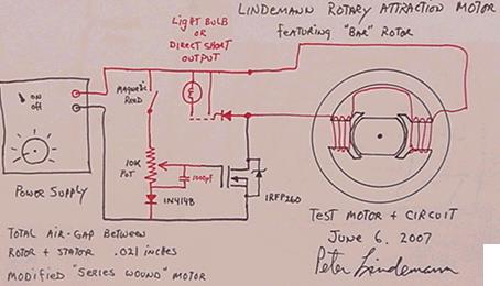
Here is a simple circuit that Doc Peter L. runs thru the connections, however you can buy scooter controllers that have the extra wires for hall or reed for a brushless motor.
For now look at this short informational video to understand your specific situation.
.....................Leave a comment:
-
Hi Memphis
Looks like it is a 24vdc golf cart motor so it is like a universal motor some call "series wound" especially since you had to remove brushes and add magnets so everything I said about universal motors apply. By removing the commutator action with it's windings in series with the outside windings you have eliminated the timing for which the motor coils fire. Therefore you will need a circuit that fires pulses based on a sensor you will need to place on the shaft.
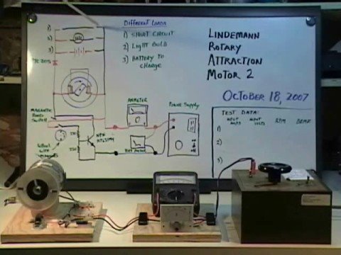
Did you see my earlier post of Peter Lindemann's simple / effective circuit for a universal motor? His little circuit does the pulsing using a magnetic reed switch plus recovers all of the collapsing field energy back to an extra battery. You could use a hall effects switch also.
Here it is and how when taking out the rotor you hook the 2 outside windings
 Last edited by BroMikey; 05-20-2022, 05:16 PM.
Leave a comment:
-
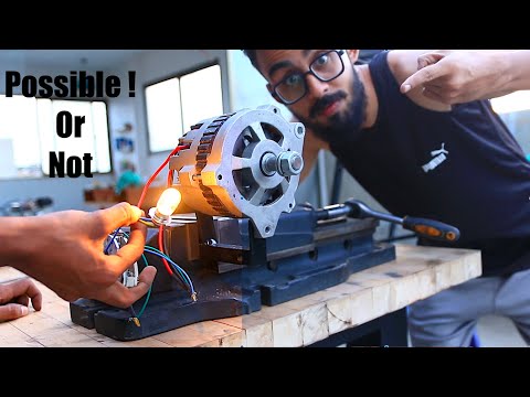
Mikey what you see disassembled is the three-phase 24v alternator of a bulldozer to which I replaced the rotor winding with magnets (so I also eliminated the brushes and the control circuit, now the output varies according to the speed of rotation, at 2500 rpm it takes out 42V.) The motor is the black one you see mounted in the photos on the right, it is a 24V, 500watt direct current.Now I need to power that pulse engine.Thanks always for the help.Leave a comment:
-
Here is one with magnets modified rotor and controller same as your 3 phase motor same as a 3 phase alternator with the rectifier removed. Everybody is doing this, this is nothing new. It works well from what I hear. You do not have a universal motor, you had a 3 phase motor that you have converted to a 3 phase DC brushless PMM ( PMM = permanent magnet motor) this is a winner.
If your motor is 220v you might be in trouble finding a controller for high voltage. I have seen up to 90vdc.
Notation: disregard all entries about universal motor controllers.
 Last edited by BroMikey; 05-20-2022, 05:55 AM.
Leave a comment:
-
Watch him, he shows you what buy and how to wire it up with a common brushless controller off of Ebay or Amazon.
Leave a comment:
-
Memphis
This is what you are doing except the outside winding in your case is not 3 phase so you can't use the RC out of the box ESC controllers that have built in timing.
Look on your motor plate for RPM, if it is 3600 the motor is two pole or 2 phase. You are creating a BRUSHLESS DC motor and your rotor windings are just like an alternator rotor.
Do you know if the motor plate says 1ph or single phase? Or is your motor a 3 phase motor?
 Last edited by BroMikey; 05-20-2022, 04:57 AM.
Leave a comment:
-
This universal motor dia is better because it shows all of the windings and how they are connected. When you chop off half the windings the resistance is less and 115v will melt the remaining winding. I want to do this myself and have been thinking about it.
Come to think about it start at 20v and go higher till the amp draw rating peaks.
You will need more than a pulse circuit you will also need the circuit to use a hall effects sensor to time the pulses. Normally the timing is done by way of the commutator.
 Last edited by BroMikey; 05-20-2022, 04:21 AM.
Leave a comment:

Leave a comment: