If this is your first visit, be sure to
check out the FAQ by clicking the
link above. You may have to register
before you can post: click the register link above to proceed. To start viewing messages,
select the forum that you want to visit from the selection below.
I realize you are making other tests and can not do a true dual rotor since shielding makes large dia 1" magnets more field directed. (see pic) Here is an example taking a picture from Thane's dual rotor video. His gap is 1/2" so you should be good to go at 1/16"
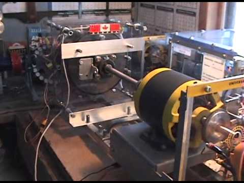
That video has a dump load of circuit waste, not even using the coils effect and his big problem is over charging the drive battery bank with the black box motor switch. Go figure.
I will also put rotors on BOTH ends of the coils to compare output once I have settled on a specific size of magnet.
That will work really great. If it does don't tear it down, keep it. Use that if you ever get another chance to show it. I mean 4 super powered coils putting out 300w each will prove a point.
It's worth having a functioning prototype. Say the grinder takes 600watts and the coils kick in and it drops to 575w but the generator coils deliver 1200w
The 2" magnet rotor isn't chewed up. You are seeing the body of the grinder behind it that may make it appear that way. One of the rotors takes 3/4" by 1" long magnets and 1" by 1" long magnets. The other rotor takes 3/4 "by 3/4" long magnets and 1" by 3/4" long magnets. The magnets just came today so I can get these rotors put together. I will REMOVE the 3/4" by 1" long magnets after testing them, before I put in the 1" by 1" long magnets. Same goes for the other rotor. Only four of one size magnet at a time for the test. I will also put rotors on BOTH ends of the coils to compare output once I have settled on a specific size of magnet.
Let me change the subject. Are these 1" magnets? By 1" long? I know the big one's are 2"
Two sizes on the other rotor, oh that's right. What in the world? Looks like the 2" magnet rotor is chewed up on the edge. The 1" should work but it depends on the coil and core
I’m betting he IS running a Variac from the wall but believes his output is much greater than his input.
input is 5 amps at 40 volts, and did he say to EACH of the coils or to all the coils in total?
500ma not 5 amps at 50v to 100v going to the two motors via flyback inverter motor switch.
Here is what I know. Standard inverters use pulse dc and that is fed into a block transformer as the final stage (Variac same) to clean up the output. Or use the variac as a rheostat to control speed either way Thane is not a God Damnn liar like he has been painted up to be by those who can't find their heads with both hands electronically
Second guess all you like, Thane says the power is all coming from the batteries
This is where beginners freak out not knowing that Pulsed DC is a form of AC. The modified inverters make my fans sound like they are rattling, that is pulsed DC coming thru a coil of wire known as a transformer. Variacs are transformers and can be a substitute for a block transformer. Electronics 101.
Back then the goal was to use table top batteries as a source and later the e-bike batteries. Thane is a genius/high level EE electrical engineer who broken away from the academic prison. That makes his a double genius. Besides he is the one with the sweaty arm pits like Edison said.
Did you hear him say "all coming from the batteries"? Because Thane is using a variac people assume it's ac from the wall. It is not ac from the wall. It's part of his flyback motor switch. It is pulse DC not AC
If he is using a Variac as you say, A Variac runs on AC. Flyback would be AC, but would provide no amps without a capacitor bank to convert voltage to amps, and there would BE no flyback until the machine was already running and up to speed. I don’t see a capacitor bank if there is one. And he would have to have the output of the cap bank regulated or he would blow up the Variac. If it is all coming from the batteries and it is, as you stated, pulsed DC, then he is either running an inverter on his batteries in order to provide the Variac with AC power to produce high voltage AC which he then puts through a bridge rectifier to get DC which he runs through a pulsing circuit to get pulsed DC, or he has several batteries connected in series and is pulsing high voltage DC to the Variac to mimic 110v AC to run it in order to produce 110 V AC output. Why bother with the Variac when you already have the batteries mimicking 110 v AC
Too many losses in those setups.
The first step would be to eliminate the Variac and use the 110 v AC provided by the simple inverter. Run THAT through a bridge rectifier to get high voltage DC and then pulse it. No Variac needed. Saves a step.
I’m betting he IS running a Variac from the wall but believes his output is much greater than his input.
input is 5 amps at 40 volts, and did he say to EACH of the coils or to all the coils in total?
That fly back/motor switch sounds a lot like the circuit Matt has for the simple motor. It fires the motor while at the same time sending the coil collapse to the charge battery.
I just watched it again. There are 6 to 8 segments of many tests. Can you imagine his frustration in delivering such a complicated array of tests that are well over the heads of most.
Very few people will perceive all of the intricate details given. I have watched this video for years and still picking up more from it.
That fly back/motor switch sounds a lot like the circuit Matt has for the simple motor. It fires the motor while at the same time sending the coil collapse to the charge battery. I will watch the video when I get a chance. It doesn’t play on my iPhone but will on my laptop. Both are Apple products.
YES YOU ARE A VERY KNOWLEDGABLE PERSON ON THE SUBJECT.
Here is an 8 year old video starting at 130rpm then 600rpm then going down to 350rpm
Be patient and pick over this short video. It answers your question above. It's a beginning
He is using only three coils but I think this old design had dual rotors as you mentioned 1/2" gaps yet it works.
Listen to the message about the flyback switch then he calls it a motor switch it ain't that hard to collect.
Did you hear him say "all coming from the batteries"? Because Thane is using a variac people assume it's ac from the wall. It is not ac from the wall. It's part of his flyback motor switch. It is pulse DC not AC
I watched the video. I understand everything Thane is talking about, and it all fits what I know about how these kinds of coils can operate. And from what I saw, it could be done with rotors on both ends of the coil rather than a C core. But I will have to try it to be sure. I hear 66 amps, but that is a pulse, and no mention of volts. Amps without volts or volts without amps mean nothing to me, as either is easy to do. It is the combination of BOTH that is meaningful. I also hear that of the three coils, two require a specific frequency to work as claimed. With a motorcycle that speeds up and slows down, traveling in the correct frequency range for operation of those coils is very iffy, which is probably why we haven't yet seen a Thane bike on the road. Maintaining the correct frequency of rotation is a heck of a lot easier in the lab than it is in real world stop and go situations. That "black box" is his computer that can monitor what is going on in the coils and decide whether to add them to or exclude them from the circuit based on the rpm at which the vehicle is turning the wheel. And his coil which requires no electrical input to provide acceleration is simply using transformer action for increased mechanical power, or "flux harvesting" to produce electricity depending on the situation. Pretty ingenious to design all that into one coil.
One of the things Matt said, and I saw when I built his simple motor, is that when the magnetic field is contained in the coil between two rotor magnets, or in Thane's case, in a "C" core, the spike you get from coil collapse is TREMENDOUS. Matt's setup doesn't even WORK with one rotor. So as a motor, and as a generator, Matt had to have rotors on both ends to produce torque AND to capture the high voltage spike from coil collapse, which can be turned into amperage by the right capacitor, or can charge the second battery faster than the first battery runs down.
From what I know about these coils, and from what Thane said in the video about WHEN his coils work and DON'T work, there is only a certain range of operation (range of speed) where everything works the way it should. Outside of that range, these become ordinary coils. I wonder if he knows how to make them work at all different ranges of speed? Doesn't sound like it from the video. That's a problem. Running a generator is easy, because you can run at constant RPM, but then you don't NEED all the fancy things these coils provide. To run a bike or a car, with variable speeds, you do. And I'm willing to bet that he is still having problems with that variable. Until he solves that problem, we aren't going to see a bike that will run forever from Thane, even though it WILL get extended run times on a charge. Cool stuff!
The C core allows for magnets on both ends of the core material at the same time.
The C core might give even MORE output and might be better for OTHER reasons.
Current testing will definitely include rotors on both ends ..
I don't know why that is. I have not built more than 1 C core coil.
Check out the coils and how the new coil is viewed. He shows a 66amp coil but that is the pulsed value when motoring but then the same coil has 7 other functions. C core coils. One C core goes on each side of a rotor and one goes on only one side of the rotor which requires a n and s magnet on each end meaning 2 magnet are skipped.
The C core allows for magnets on both ends of the core material at the same time. You can accomplish the same thing with dual rotors and not have to have your core material in that special “C”configuration. The C core might give even MORE output and might be better for OTHER reasons.
Magnets on both ends of the coils seem to “trap” the flux between the magnets causing the coils to output more. I have seen it with both motor and generator coils in a dual rotor machine. My very FIRST generator build was dual rotor. I may end up going back to that configuration, and if I do, it will be a 3 rotor machine so I can have two sets of coils with a rotor between each set and rotors on both ends. But I will make that decision when I finish the testing I am doing now. Current testing will definitely include rotors on both ends of the coils with this new core material.
But he can't tell much and he knows about the core material too. Did you see a few of Thane's in person demos where ALMOST hands the C coil to a guy but wont let it out of his hand? He doesn't want to have one come up missing.
It's a secret. You might sign another NDA and find out and if your friend tells you he might be charged. You can figure this out but I say the C core shape is the key to reducing coil size and increasing amperage. 5 amps is a huge difference.
The black box motor recovery is always on during demo's this is another secret
Leave a comment: