If this is your first visit, be sure to
check out the FAQ by clicking the
link above. You may have to register
before you can post: click the register link above to proceed. To start viewing messages,
select the forum that you want to visit from the selection below.
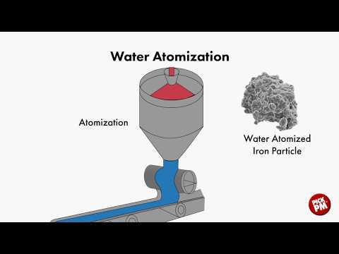
I can buy a 50 ton bottle jack to press metal powders with wax to then roast in a $50 propane forge to get a fe-si rotor shape fe-si powders are cheap and come in 3% all the way to 50%
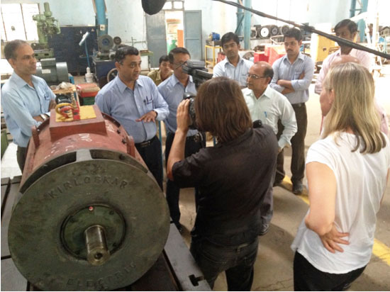
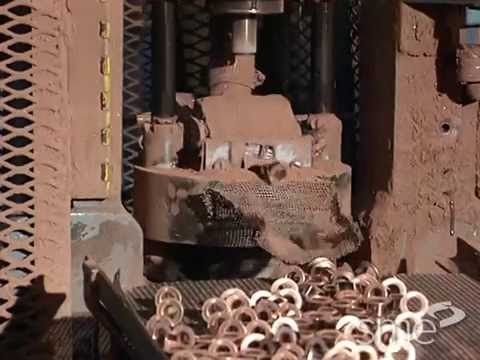
Most metal parts today are made this way, by press or 3D printing. Before heating the green part red they break like a hard dried out cookie. It cost twice as much to pour liquid metal into molds. This gear shape is 84mm or just over 3"
Soft magnetic composites (SMCs) were prepared from three different ferromagnetic powder particles: iron powder ASC 100.29, spherical FeSi particles and vitroperm (Fe73Cu1Nb3Si16B7) flakes. Two types of hybride organic-inorganic phenolic resins modified with either silica nanoparticles or boron were used to design a thin insulating layer perfectly covering the ferromagnetic particles. Fourier transform infrared (FTIR) spectrometry confirmed an incorporation of silica or boron into the polymer matrix, which manifested itself through an improved thermal stability of the hybrid resins verified by Thermogravimetric-differential scanning calorimetry (TG-DSC) analysis. The core-shell particles prepared from the ferromagnetic powder particles and the modified hybrid resins were further compacted to the cylindrical and toroidal shapes for the mechanical, electrical and magnetic testing. A uniform distribution of the resin between the ferromagnetic particles was evidenced by scanning electron microscope (SEM) analysis, which was also reflected in a rather high value of the electrical resistivity. A low porosity and extraordinary high values of mechanical hardness and flexural strength were found in SMC consisting of the iron powder and phenolic resin modified with boron. The coercive fields of the prepared samples were comparable with the commercial SMCs.
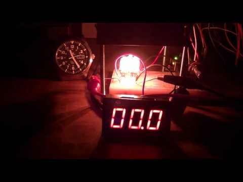
I watched that video before. I watched it right after it was FIRST posted. I watched it again when YOU posted it and made claims that it produced all this ELECTRICAL power, which I knew to be impossible, having built MANY similar devices. If it is TORQUE you are looking for, I would recommend the Ron Cole motor rather than the Lindemann attraction motor. It is MUCH easier (and cheaper) to build, and I know from experience that when you fire a coil to create an electromagnet that is located BETWEEN TWO PERMANENT MAGNETS, you get the advantage of MUCH GREATER TORQUE!!!! EXPLOSIVE torque. Ron's design also has the MAGNETIC LOOP so you do NOT have CEMF or back EMF and you CAN capture the collapsing spikes from TWO coils instead of one. The size of the coils determines the collapsing spike.
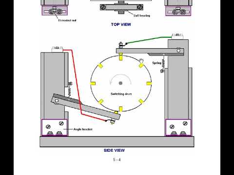
The motor I have seen that I believe to be BETTER than both of these, ALTHOUGH I WOULD MAKE NO SUCH CLAIM UNTIL I SAW A SIDE BY SIDE COMPARISON is the Matt Jones simple motor. It fires the coils between two permanent magnets as does the Ron Cole device. It uses LARGE coils which give a lot more electrical output and torque. You can have as MANY as you want, limited only by the size of your rotor. I could be mistaken, but I believe the major difference is that Matt WANTS the CEMF because instead of allowing it to fight the incoming current and voltage, he figured out a way to channel it OUT of the circuit and use it to supply the load. So there is NO bogging down when it is put under load. (no Lenz) One of the ways he found to DO this involves sending the output through a spark gap, which is where the POINTS I showed come in. His setup outputs considerably more power because you get the spike from collapse that Lindemann and Cole are using from TWO coils instead of one, PLUS the addition of the generated CEMF as electrical output. A version of this motor was actually my very first build of anything mechanical that had to do with free energy. I contacted Matt after I read his pdf, and he walked me step by step through the construction of this motor. I saw that it could charge one battery faster than it discharged another, and by switching batteries back and forth, I saw gains in BOTH. Matt also developed a circuit for it that you use to run one battery to charge another, and then flips to run off the charged battery and charge the discharged battery. It could be connected to an Arduino and do it automatically. Depending on the size of your rotors, you could have 2, 4, 6 or 8 coils, which would definitely ADD to the torque of the motor and the power output. He figured 4 coils for 1/2 hp if I remember correctly. Bob French and I are currently in the process of building a LARGE version of this motor. I also have a couple 6" rotors I am working on putting together a small version with, and Bob already HAS a small version with two coils between the rotors for the motor, and then Lenz free generator coils on the OUTSIDE of the rotors to generate power. If he will take a video of it, I will post it.
Silicon steels are ferritic alloys of iron and silicon that have magnetic properties which make them useful in motors and transformers. The silicon additions improve magnetic softness and increase the electrical resistivity.
This analysis of energy produced is NOT the electrical energy that comes out of the device
How about YOU learn to analyze the data before you make claims.
Yes that is true but my goal is to come up with a motor to drive the generator head with better than COP>1
Let's dispense with the theater. I was thinking up ways to make 2 "S" rotors when I thought of bee bee's and magnetite pressed together by resin. I have these "C" shapes for the coils so my question is would the bee bee's and magnetic sand hold together at high speeds and would that get hot? probably should add some micro fibers to the mix.
8 COP motor could raise the over all eff. and from what Peter said these motors have huge torque so that might over come a ton of cogging losses. COP 8 for the motor that generated power to boot. Not bad. So you finally watched the video?
See what you put me thru to get you to watch this 17 year old video? Maybe the generated output won't run your house instead say all the electronics with generator lighting?
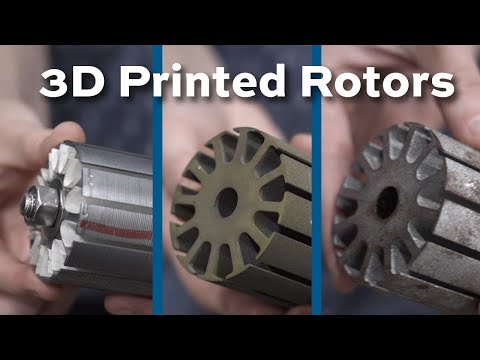
What do you think about the "S" rotor? I don't have a stamping plant for stacking laminates and I need a solution.
Also having an 8 COP motor means you can connect a conventional scooter motor to it to generate 8X the power you put in. With generator losses 6X. IT'S A GOOD GIFT LIKE THE ZERO FORCE MOTOR.
The Murray ellipse could be cut with chop saw, maybe it's the same thing?
The modified motor didn't even come close to this.
This analysis of energy produced is NOT the electrical energy that comes out of the device that can be used to charge a battery or run your home, as you CLAIMED. It is a COMBINATION of the energy gained from the collapsed spike PLUS the mechanical energy supplied by the shaft. So VERY LITTLE of it is actual ELECTRICAL energy and MOST of it is MECHANICAL energy. How about YOU learn to analyze the data before you make claims.


Leave a comment: