Announcement

Collapse
No announcement yet.

Radiant spike puts out more than current

Collapse
X
 
  • Filter
  • Time
  • Show
Clear All
new posts

  • Originally posted by Bob Smith View Post
    ... Because of this potential difference between turns, there must also forces of attraction between them; ...


    Bob, you've lost me.

    In the highlighted region below, how can this be considered attraction?

    You are meaning electrostatic attraction correct? Not magnetic?


    My thinking is if the voltage/current ratio is specifically chosen, the electrostatic force and the magnetic force are in perfect balance. At this point we have something rather unusual taking place.
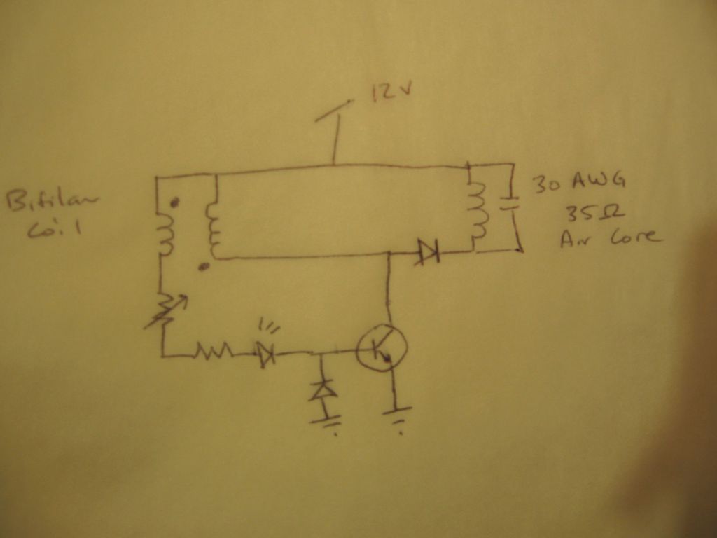
    Attached Files
    Last edited by Dog-One; 12-30-2015, 02:45 AM. Reason: Added content.

    Comment


    • All right, so I'm trying to duplicate what minoly was showing in the first video. My circuit as shown resonates, but burns a lot of power. The transistor gets quite hot and requires a heat sink. Second, the lowest frequency I seem to be able to get is around 150 Hz. I'm pretty sure there's something I'm missing. I've tried numerous capacitors and resistances. What more do I need to duplicate the original circuit?

      Thanks!

      Comment


      • Originally posted by Bob Smith View Post
        I hope I'm not being a pain, but I'm going to try to proceed from what I have observed, guided by what I have read, to state how I see things...

        According to Tesla, there is potential difference present between the turns in a coil; there is storage of charge, or capacitance. See his patent for electromagnets for details. Because of this potential difference between turns, there must also forces of attraction between them; and taking this logic one step further, perhaps interaction with the dielectric along the coil between the windings, in a manner similar to that which occurs at the bloch wall or dielectric plane at the coil's midpoint.

        What could this mean? If the dielectric is interacting with the coil between each of the windings as well as at the overall midpoint, then these areas are points at which charge enters the coil from the dielectric to produce the Lenz' Law (opposing spike) effect. IOW, Lenz' Law is a dielectric's response to an initial pulse in the coil.

        Bob
        You see what you see. I see something different. In the end, I hope we land on the same page, capable of demonstrating the same effects.

        On that note....I wish you well and hope you find what you seek.


        Regards

        Comment


        • Originally posted by Dog-One View Post
          At this point we have something rather unusual taking place.[/LEFT]
          I find it to be the point maximum opposition to change in flux. It is the point of maximum opposition to change in flux, because flux at this point is zero.

          Being the point of maximum opposition to change in flux (current), it is likewise the point of maximum induced potential.

          "Inductance is the characteristic of an electrical circuit that makes itself evident by opposing the starting, stopping, or changing of current flow......

          Inductance is the characteristic of an electrical conductor which opposes a change in current flow......

          The unit for measuring inductance, L, is the Henry, h. An inductor has an inductance of 1 Henry if an emf of 1 volt is induced in the inductor when the current through the inductor is changing at the rate of 1 ampere per second. The relation between the induced voltage, inductance, and rate of change of current with respect to time is stated mathematically as....."

          Where others see distributed capacity, I see the seat of inductance. Inductance, a distributed aspect in a coil, takes on different attributes within electrodynamic machines. It has a specific space geometry and distribution, and a direct relation to frequency. These realizations lead one to seek out where capacitance really is, and its relation to inductance. When it was found, I was in awe, the geometry of our systems will never allow true resonant operation, as inductance and capacity manifest in such a manner that phase alignment without an intermediary is impossible. Fortunately...there is hope......

          My dogma.....


          Regards

          Comment


          • I may be trying to out guess Bob without enough information.
            My idea based on what I read is that a high impedance coil such as a 10kV trigger coil
            is driven by a positive pulse is housed inside a glass jar. The glass jar defining the boundry condition.
            The jar outside surface should attract the opposite charge.
            Last edited by mikrovolt; 12-30-2015, 01:41 PM.

            Comment


            • Erfinder,
              Thanks for your helpful and respectful responses. Some observations of mine below.

              Originally posted by erfinder View Post
              I find it to be the point maximum opposition to change in flux. It is the point of maximum opposition to change in flux, because flux at this point is zero.
              Maybe I'm off here, but the point of maximum opposition to change in flux is top dead center (TDC) of a coil (in a generator) - where the zero crossing occurs. This would be the midpoint of the coil, commonly known as the bloch wall, would it not?

              Being the point of maximum opposition to change in flux (current), it is likewise the point of maximum induced potential.
              "Inductance is the characteristic of an electrical circuit that makes itself evident by opposing the starting, stopping, or changing of current flow......

              Inductance is the characteristic of an electrical conductor which opposes a change in current flow......
              Where others see distributed capacity, I see the seat of inductance. Inductance, a distributed aspect in a coil, takes on different attributes within electrodynamic machines. It [inductance] has a specific space geometry and distribution, and a direct relation to frequency. These realizations lead one to seek out where capacitance really is, and its relation to inductance. When it was found, I was in awe, the geometry of our systems will never allow true resonant operation, as inductance and capacity manifest in such a manner that phase alignment without an intermediary is impossible. Fortunately...there is hope......
              Love it.

              Comment


              • Originally posted by Dog-One View Post

                Bob, you've lost me.

                In the highlighted region below, how can this be considered attraction?

                You are meaning electrostatic attraction correct? Not magnetic?


                My thinking is if the voltage/current ratio is specifically chosen, the electrostatic force and the magnetic force are in perfect balance. At this point we have something rather unusual taking place.
                Hi DogOne
                Thanks for the clarification. I'm feeling my way along here. Every small step of understanding opens doors to new questions. I know what Tesla says in the Coil for Electromagnets patent I quoted. I was trying to understand further what the potential difference between individual turns might mean. Not sure I'm getting it all right, and readily defer to the experts and what I see.

                I like your last statement - to me, it points in the direction of resonance. According to EPD, resonance separates amperage/magnetism from voltage/dielectricity in a coil.

                I've seen that a high impedance coil at resonance produces some interesting effects. I confess that I don't understand all of what is implied there. Though, it would seem to me that resonance in a hi-impedance coil means raised voltage output (presumably via influx from the dielectric realm), but I don't see increased current (amperage) output.

                Coming back to the coil midpoint (dielectric plane/bloch wall), I keep thinking about JB's point about vectors entering the coil at that place, and wondering what it might mean for achieving a maximum interaction of the coil with the dielectric. As Erfinder mentioned, there is something else, an intermediary needed:
                the geometry of our systems will never allow true resonant operation, as inductance and capacity manifest in such a manner that phase alignment without an intermediary is impossible. Fortunately...there is hope......
                This gives me hope of progress.
                Bob

                Comment


                • GaussBusters

                  Originally posted by Dog-One View Post

                  In the highlighted region below, how can this be considered attraction?


                  Hi Dog-,

                  Mind if I comment? These wires are attracted to each other when carrying current. Here are a couple references:

                  Principles of Magnetism | Magnetic Products and Services

                  Forces between currents.


                  Hope that helps,

                  bi
                  Attached Files

                  Comment


                  • 1 wire (as i a coil) vs. 2 wires (as in the picture)

                    Originally posted by bistander View Post
                    Hi Dog-,

                    Mind if I comment? These wires are attracted to each other when carrying current. Here are a couple references:

                    Principles of Magnetism | Magnetic Products and Services

                    Forces between currents.

                    Hope that helps,

                    bi
                    There is a simple way to verify how the force acts between turns: wind a few turns on single layer using a cylinder then take the cylinder out. Lay the coil with all its turns loose on the table and energize it with a battery. Do the coil's turns spread or come together?

                    Regards.
                    Last edited by barbosi; 12-30-2015, 07:59 PM.

                    Comment


                    • Originally posted by barbosi View Post
                      There is a simple way to verify how the force acts between turns: wind a few turns on single layer using a cylinder then take the cylinder out. Lay the coil with all its turns loose on the table and energize it with a battery. Do the coil's turns spread or come together?

                      Regards.
                      I would say, "It depends."

                      Are the magnetic forces dominate or the electrostatic ones?

                      Erfinder is on to something, something I know I have overlooked. If you take the individual windings of a coil, their "interwinding capacitance" is on the order of fractions of picofarads. I for one have always ignored such small capacitances. Bad assumption.


                      I think we truly need to re-evaluate the geometry and possibly the materials we have been using.
                      Last edited by Dog-One; 12-30-2015, 10:59 PM.

                      Comment


                      • Between the turns in the image I posted you will experience repulsion.

                        Don't take my word or anyone's word for it, perform the necessary tests and see it for yourselves.

                        The field relations between the turns in the solenoid are not the same as those between two parallel conductors carrying current. In the former you have one conductor carrying current and in the latter you have two....the comparison makes no sense.

                        It is not my job nor anyone else's job to get into why they are not the same, again here simple tests that you make up and do yourself yield all the information you will need for clarity.


                        Regards

                        Comment


                        • Originally posted by Dog-One View Post
                          I would say, "It depends."

                          Are the magnetic forces dominate or the electrostatic ones?

                          Erfinder is on to something, something I know I have overlooked. If you take the individual windings of a coil, their "interwinding capacitance" is on the order of fractions of picofarads. I for one have always ignored such small capacitances. Bad assumption.


                          I think we truly need to re-evaluate the geometry and possibly the materials we have been using.
                          Most experiment with solid state systems, I decided long ago that I could learn more about the nature of the field by exploring motors and generators.

                          We are informed of what inductance is, how it relates to frequency, how it's not constant, varying with frequency, reluctance, and saturation. We are informed of how it relates to the number of turns in a conductor, and current operating in that conductor. No such relation is mentioned regarding capacitance. I find that strange. The only capacitance we are informed of is the distributed capacity. The distributed capacity is an artifact born out of geometry. The value is orders lower than the actual capacity of the coil. I found the capacity, its all about perspective, it was there the entire time, we cannot see it for reasons too numerous for mentioning. Finding it means reevaluating everything. After you recognize it, you recognize that the manner in which we generate today is in a word.....wrong.

                          We have identified where the seat of inductance is from a geometric stand point, and done so in a totally non scientific manner, now we need to find the seat of capacity, and experience for yourselves how the two are not in phase, and as such, will never give us what we are all after....namely....

                          the key to conversion. What I mean here is the systems as they are only generate reactive power because the system by design is setup to produce reactive power......


                          Regards

                          Comment


                          • Originally posted by bistander View Post
                            Both these conductors carry current, I1 and I2. If one has no current, then the I1 * I2 product is zero and there is zero force.

                            edit: It doesn't matter if I1 and I2 are the same current or if they are from seperate sources.
                            Last edited by bistander; 12-31-2015, 07:14 PM. Reason: Reread his post

                            Comment


                            • Coil test

                              Originally posted by barbosi View Post
                              There is a simple way to verify how the force acts between turns: wind a few turns on single layer using a cylinder then take the cylinder out. Lay the coil with all its turns loose on the table and energize it with a battery. Do the coil's turns spread or come together?
                              Good idea. So I just did it. First used #18 wire and about a 2" diameter. 12Volt battery. No reaction and soon got too hot to handle. Changed to #14 wire wrapped around a ballpoint pen and slid off. About 8 turns. Strong 12V battery again. Nothing at first. But as the stiff insulation softened as it warmed, the coil showed compression when current flowed and relaxation when the current stopped. Unmistakable attraction with current. It required a substantial amount of Amps. I'll repeat with ammeter later. (edit) Meter read 500-600 Amps.

                              This doesn't take a lot of equipment and took me about 15 to 20 minutes. I encourage you to give it a try.

                              Regards,

                              bi
                              Last edited by bistander; 07-22-2020, 04:12 AM.

                              Comment


                              • All this talk about inductance and parallel conductors reminded me of an event that I saw several years ago. Some of this information may be helpful to this discussion or maybe not. But I think it is at least an interesting story.

                                My boss sent me to oversee some outside contractors as they started up this new huge bell furnace their company had built. This thing was about 15 feet tall and about 10 feet in diameter with as I remember about 100 kilowatts of resistance heat elements in the side walls. It was to be used to heat treat rocket motors for the navy.

                                When they turned on the power the whole unit was making a very loud humming noise and just didn't seem right. One of their engineers said to turn it off and asked if I could get a large clamp on ammeter.

                                When I came back with the ammeter that would read several thousand amps he had them turn the unit back on. He then proceeded to clamp the ammeter around the OUTSIDE of this large flexible conduit that was running up the outside of the furnace. The ammeter went all the way to the peg. Also the flexible conduit started to smoke it was getting so hot.

                                I need to add that there were three of these large flexible conduits running up the side of the furnace. Can you guess what they had done wrong?

                                I don't want to spoil it for those of you that would like to try and figure it out so I'll put the answer in my old thread about open discussion for projects on this forum.

                                I will add that I had decided to leave this forum because there was nothing useful going on here. I now see there are at least two serious threads abuot building and a couple of more about serious discussion of theory. So I'll stick around for a while in hopes there is some life left in this forum for serious work.

                                Respectfully,
                                Carroll
                                Just because someone disagrees with you does NOT make them your enemy. We can disagree without attacking someone.

                                Comment

                                Working...
                                X