If this is your first visit, be sure to
check out the FAQ by clicking the
link above. You may have to register
before you can post: click the register link above to proceed. To start viewing messages,
select the forum that you want to visit from the selection below.
Announcement
Collapse
No announcement yet.
The Ultimate Electro-Mechanical Device to Harness Gravitational Potential
This a good set but of course something in your case would be quite a bit larger.
There's a lot of methods for distributing weight across the B field of magnetic assembly. You can tighten the placement on the radius of the outer stator.
In the above set he has them at 60 degrees all the way around and where to carry more weight you might want to use 20 degrees across the bottom 180 degrees.
Of course the tighter they all are together the less chance of movement.
Then you always have to have a small points of contact but that can be real small and greased you would never feel the friction.
snip<
I could get these water jet cut from any material...... Would aluminium be the best choice?
snip<
Best regards,
Paul
I don't think I've got a clear picture of exactly what design you have in mind so this may be irrelevant but aluminum like copper will create a drag per Lenz on any magnets if they are in motion near the aluminum.
There is no important work, there are only a series of moments to demonstrate your mastery and impeccability. Quote from Almine
This is why I decided to experiment with large ferrites just to work everything out. Then when its optimized switch to neos of the correct strength depending on application.
The arrangement drawing isn't finished.
What I wanted to add was a way of holding the magnets with a piece inside each one of the diameters of the magnets, that is adjustable on a slide, so it can be adjusted for an air gap.
With the magnets being the same size allows a concentration of the fields as I see them.
Basically what I see is we are trying to create a magnetic plane for all the bearings to align too.
I would also incorporate magnets on the shaft and inside the housing to prevent sideways movement of the axle.
I don't think I've got a clear picture of exactly what design you have in mind so this may be irrelevant but aluminum like copper will create a drag per Lenz on any magnets if they are in motion near the aluminum.
Not sure what the best material to use for the mountings.
Was fishing for ideas.
Yeah the way magnets react when falling through copper and aluminium tubes is real magic.
Aluminum will not have effect as long as you do not run the face of magnet perpendicular to the aluminum.
Your not going to be able use magnetic force to hold the thing in place you will have to have a point against something solid.
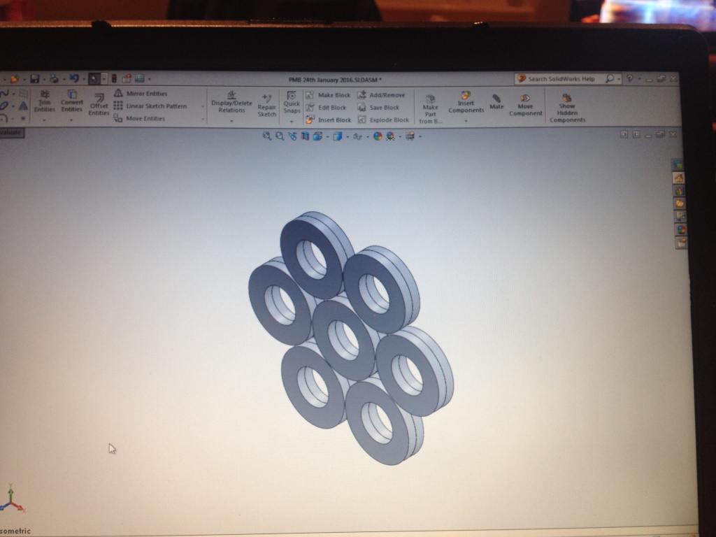
I'll do some drawings in the morning. The model you show will work but its even. You do not want that with heavy weight. You want more on the bottom then the top.
Aluminum will not have effect as long as you do not run the face of magnet perpendicular to the aluminum.
Your not going to be able use magnetic force to hold the thing in place you will have to have a point against something solid.
I'll do some drawings in the morning. The model you show will work but its even. You do not want that with heavy weight. You want more on the bottom then the top.
Matt
Not totally sure on the aluminum bit...
Maybe better to use acetal or nylon.
If each magnets distance is adjustable then the magnetism can be adjusted so the strength is focused more on the bottom.
If the shaft is tapped and threaded both sides and a flat disk magnet fixed to each end then surely two opposing disk magnets each end will lock the shaft in total suspension?
If each magnets distance is adjustable then the magnetism can be adjusted so the strength is focused more on the bottom.
If the shaft is tapped and threaded both sides and a flat disk magnet fixed to each end then surely two opposing disk magnets each end will lock the shaft in total suspension?
Best regards,
Paul
No because you will never get 2 even magnets. It also only works cause its pushing in one direction. If you try to center it the shaft will go one way or the other.
You'll have to have very small point touching something. Very small though. And you can lower any drag caused by using end magnets but they will not suspend totally.
I'm sure I've seen a video on YouTube and there was no friction. The axle was completely suspended. I just had no clue of the magnetic field arrangement at the time.
 Tweet
Tweet


Comment