Announcement

Collapse
No announcement yet.

Lockridge, or 2x Von Siemens ?

Collapse
X
 
  • Filter
  • Time
  • Show
Clear All
new posts

  • Lockridge, or 2x Von Siemens ?

    Hi Pals,

    Since this might be different from the thread about the Lockridge's device as envisionned by our friend and mentor Peter Lindemann, I'm opening this new thread as an alternative path.

    I'm currently wondering if the Lockridge device could have been a double Werner von Siemens device with a capacitor in the middle...

    See here why, and please feel free to give your opinion :

    https://www.siemens.com/history/en/n...principles.htm


    Here is an an "exploded view diagram" :


    Thanks.
    Last edited by marseye; 03-23-2016, 11:31 AM.
    -*-*-*-*-*-*-*-*-*-*-
    M.E. Who else ?...

  • #2
    There, he writes some broad considerations about his discovery :

    http://www.siemens.com/recollections...ollections.pdf

    (in the part about his dynamo-electric machine) :

    from page 351 :
    (...) the
    question occupied my mind whether it would not be possible by suitable employment of the so-called extra current to intensify considerably the induction current.
    It became clear to me that an electromagnetic machine, whose working power is very much enfeebled by the induced currents arising in its coils, because these induced currents considerably diminish the energy of the galvanic
    battery, might conversely strengthen the power of the latter if it were forcibly turned in the opposite direction by an external force. This could not fail to be the case, because the direction of the induced currents was at the same time
    reversed by the reversed movement. In fact, experiments confirmed this theory, and it appeared that there always remains sufficient magnetism in the fixed electro magnets of a suitably contrived electromagnetic machine to produce
    the most surprising effects by gradually strengthening the current generated by the reversed rotation.
    This was the discovery and first application of the dynamo-electric principle underlying all dynamo-electric machines.
    (...)
    -*-*-*-*-*-*-*-*-*-*-
    M.E. Who else ?...

    Comment


    • #3
      Originally posted by marseye View Post
      Hi Pals,

      Since this might be different from the thread about the Lockridge's device as envisionned by our friend and mentor Peter Lindemann, I'm opening this new thread as an alternative path.

      I'm currently wondering if the Lockridge device could have been a double Werner von Siemens device with a capacitor in the middle...

      See here why, and please feel free to give your opinion :

      https://www.siemens.com/history/en/n...principles.htm


      Thanks.
      Marseye,
      Could you break this comparison down a little more?

      I tried for a year to build and fund the Lockridge device with limited success so I'm really interested in your comparison. I spent hours studying John Bedini and Peter Lindemann videos but neither helped much. At lest for me.

      Hope you have more success than I did.
      wantomake

      Comment


      • #4
        Hi Wantomake,

        it's been years now that I'm playing sometimes with some ideas, hoping to get rid of the heavy baterries. No success for me neither.

        Being fed of browsing the internet for every "Lockridge" occurence that I could find, and these mostly describing again and again the same thoughts and considerations (but with no successfull replication in sight either), I always scratched my head about who, previously to the soldier Lockridge who found a device, could possibly have laid the bases for the device to exist.

        Obviously, it had to be at least a german, or more broadly an european (Internet was quite...laggy in these days , and more : it was a severe war time and zone).
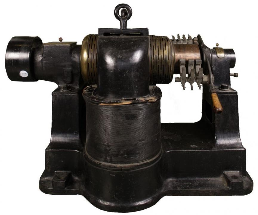
        Bedini showed us that solid magnets weren't the path to follow for the Lockridge device (LD). He clearly stated that there was enough residual magnetism in electro-magnets to start with.

        And lately, i just found this Ernst Werner von Siemens who's said to be the father of the self excitable dynamo-electric generator, in which the electro-magnets are gradually strenghtening their curent by reverse rotation !
        Of course, one has to consider that von Siemens was thinking of rotating the shaft from an external source (pulley).

        But, hey, can't we extrapolate better now, thinking about the LD with 2 electro-magnets poles pairs, which was enough to hand start, then was slowly, gradually, continuing to gain speed ? Any load had to wait for 10 minutes before it could be plugged in.

        And Von Siemens states that his reinforcing current effect was obtained from the "reversed rotation" event... Remember that all the coils are in series, by each electro-magnet pair, relative to a facing drum on the turning shaft. ? (one can also think : by NS electro-magnetic circuit)

        And LD had S/N/N/S poles arrangements ? Is that coincidence ?

        I'm quite broke these days, and have no workshop at all. So I can just be dreaming.... But I can't help my mind racing...

        Talented workmanship welcome ! Tests needed. Please help, pals.


        Can we picture this with 90° apart electromagnets, S/N/N/S , with pairs made of opposite poles ?
        Last edited by marseye; 03-23-2016, 12:19 PM.
        -*-*-*-*-*-*-*-*-*-*-
        M.E. Who else ?...

        Comment


        • #5
          And about the tri-fillar coils, Peter Lindemann had thought of an impedance matching system.

          But what if it was in fact a two-fillar coils, one being center tapped ? Quite a radiant transformer, maybe... We must keep in mind that this was a (burst) dc generator, which was common in these times. But if there was current growing, sparks (or so) could occur, right ?

          Just my 2 cents again.
          Last edited by marseye; 03-23-2016, 11:27 AM.
          -*-*-*-*-*-*-*-*-*-*-
          M.E. Who else ?...

          Comment


          • #6


            Machine dynamo-électrique à courant continu et induit Siemens
            Période d'utilisation: 1875-1900
            Fabriquant: Société Alsacienne de Constructions Mécaniques (SACM)
            (...)
            Cette machine dynamo-électrique de Gramme de type supérieur, en diffère par le bobinage de son induit qui est réalisé en tambour plutôt qu'en anneau. Elle a été mise en œuvre afin d'optimiser la puissance du champ magnétique inducteur. Son principe général est de transformer l'énergie mécanique (rotation) en énergie électrique grâce au phénomène d'induction. D'aprés l'inscription sur la machine "Belfort G56", il s'agirait d'une dynamo bipolaire du type G fabriquée par la Société Alsacienne de Constructions Mécaniques (SACM) de Belfort à partir de 1895. Cette machine dynamo-électrique comporte : un inducteur fixe à deux bobines dont les noyaux sont fixés sur le socle de la machine et sont munis de pièces polaires entourant l'induit situé à la partie supérieure de la machine ; un induit, mobile autour d'un axe horizontal, bobiné en tambour et relié à un ensemble collecteur-balais, lesquels balais sont réglables manuellement en position. L'induit est protégé par une grille en cuivre. L'inducteur alimenté en courant continu produit un champ magnétique au niveau des conducteurs de l'induit. Ceux-ci, lorsqu'ils tournent, sont le siège de forces électromotrices alternatives qui sont transformées en une tension quasi-continue par l'intermédiaire de l'ensemble collecteur-balais. Cette machine peut donc fonctionner en génératrice et délivrer un courant continu, lorsque son induit est entraîné en rotation. Inversement, lorsque l'induit est alimenté à travers l'ensemble balais-collecteur par une source extérieure à courant continu, elle peut aussi fonctionner en moteur.

            Utilisation : Cette machine était utilisée en moteur ou générateur pour la conversion électromécanique. L'induit en tambour a été inventé par W. Siemens dès 1875 mais son utilisation ne s'est généralisée qu'à la fin du dix neuvième siècle.
            "Le principal avantage de ce type de bobinage réside dans une meilleure utilisation du fil de cuivre; par contre il présente l'inconvénient du croisement des fils, ce qui augmente les difficultés de construction et de réparation…"
            Hauteur: 82cm
            Longueur: 110cm
            Poids: 68kg

            src: Machine dynamo-électrique Ã* courant continu et induit Siemens
            Siemens Dynamo-electric induced DC machine
            Period of use: 1875-1900
            Manufacturer: Alsatian Society of Mechanical Constructions (SACM)
            (...)
            This dynamoelectric machine of Gramme superior type differs in its armature winding which is made of drums rather than rings. It was implemented to optimize the power of the inductive magnetic field. Its general principle is to convert mechanical energy (rotation) into electrical energy through induction phenomenon. From the "Belfort G56" registering on the machine , it would be a bipolar dynamo type G manufactured by the Alsatian Society of Mechanical Constructions (SACM) Belfort from 1895. This dynamo-electric machine includes : a fixed inductor with two coils whose cores are attached to the machine base and are provided with pole pieces surrounding the armature located at the upper part of the machine; a movable armature about a horizontal axis, wound with drum fashion and connected to a manifold assembly of brushes, which are manually adjustable in position. The armature is protected by a copper grid. The inductor supplied with direct current generates a magnetic field at the conductors of the armature. Thereof, when rotating, are the site of alternative electromotive forces which are transformed into a quasi-DC voltage via the collector-brushes.

            This machine can operate as a generator and is outputting a direct current, when the armature is rotated. Conversely, when the armature is fed through the entire brush collector by an external source to DC, it can also operate as a motor.


            Use : This machine was used as motor or generator for electromechanical conversion. The inductive drum armature was invented by W. Siemens in 1875 but its use didn't become widespread until the late nineteenth century.
            "The main advantage of this type of coil is a better use of the copper wire, but has the disadvantage of crossing threads, which increases the difficulties of construction and repair ..."
            Height: 82cm
            Length: 110cm
            Weight: 68kg
            Hope this translation attempt helps.
            Last edited by marseye; 03-23-2016, 07:35 PM.
            -*-*-*-*-*-*-*-*-*-*-
            M.E. Who else ?...

            Comment


            • #7
              Here is the shematic of a drum armature. I couldn't insert it directly, nor publish it anywhere, so it's on my GDrive.
              -*-*-*-*-*-*-*-*-*-*-
              M.E. Who else ?...

              Comment


              • #8
                Many types

                Originally posted by marseye View Post
                And about the tri-fillar coils, Peter Lindemann had thought of an impedance matching system.

                But what if it was in fact a two-fillar coils, one being center tapped ? Quite a radiant transformer, maybe... We must keep in mind that this was a (burst) dc generator, which was common in these times. But if there was current growing, sparks (or so) could occur, right ?

                Just my 2 cents again.
                M.E.,
                Nice picture and translation. I guess.

                The tri-filar coil was wrapped onto same spool as the capacitor. My experiments (many) with a size that fits over the Lockridge housing. I believe this is the power source of the machine. I built exactly as John Bedini discussed on the video. But didn't use copper for the capacitor. Instead for fund reasons used aluminum duct tape 4" wide with wax paper.
                Sad but not surprised, the capacitor would not hold much voltage or be influenced by the surrounding tri-filar coil.
                The motor/generator did produce voltage but the coil capacitor would not build up or hold enough amperage to turn the motor.

                Funds, knowledge base, shop machinery, and time all slowed that project to a stop.

                But it really was great to learn and experience from that project.
                wantomake

                Comment


                • #9
                  marseye, like you I have spent much time on this device, and finding little historic evidence and information I gave up on that type of research. Instead I studied the pictures of the device John Bedini had, looked at the geometry and started to test different aspects of what I could see.

                  There is enough that works in the pictures for me to believe it is a real device and I believe I have some of it worked out. I do believe residual magnetism is enough to get it going but being attached to a battery would guarantee instant energisation, and once energised, no battery would be needed. Its a bit like a diesel welding set, once the generator is turning and there is a circuit the machine will self energise.

                  The Drum armature is actually not greatly different from what I have proposed and tested. I will need to study the Siemens Device for a while to fully understand it.

                  As for the use of the trifler coil there are many possibilities and just as with the rest of the machine, I believe trial and error is the way to identify its exact function. One thing I have established is that the generation assists the torque and this as been confirmed by wantomake amongst others.

                  Comment


                  • #10
                    Hi mbrownn,

                    I have been away from this forum for a long time... Could you please post a link to what you have proposed and tested, just for reference, or through pm?

                    @ all : everything I have reported here are my latest findings, just for info. I think this is all complementary to John Bedini's explanations (except for the comment about the trifiler coil, which was just an instant thought of mines).

                    I'm just hoping (like everyone here thinking that it can happen) that we can find this holy grail soonner or later.

                    Cheers
                    Last edited by marseye; 03-23-2016, 05:52 PM.
                    -*-*-*-*-*-*-*-*-*-*-
                    M.E. Who else ?...

                    Comment


                    • #11
                      Thinking out loud : Can't we see, in the Siemens device, sort of a Leedskalnin closed horseshoe too ?... (with an electro-magnetic shaft turning inside the bottom leg)
                      Last edited by marseye; 03-23-2016, 10:41 PM.
                      -*-*-*-*-*-*-*-*-*-*-
                      M.E. Who else ?...

                      Comment


                      • #12
                        From what Mbrownn and I have figured out is that the geometry of the coils is the key to get the motor running. It starts out slow and picks up speed as it rotates to about 5000 rpms. You can set the brushes so that you have to give it a spin for it to start rotating. Now if you had a flywheel on it you would either need to spin it by hand or use a pull rope to get it going.
                        The tri coil is where Im stuck at right now. Been a couple of monthe since I last worked on it.

                        Comment


                        • #13
                          Originally posted by Hiwater View Post
                          From what Mbrownn and I have figured out is that the geometry of the coils is the key to get the motor running. It starts out slow and picks up speed as it rotates to about 5000 rpms. You can set the brushes so that you have to give it a spin for it to start rotating. (...)
                          Ok, Hiwater. I need to understand : not yet a self-runner, right ? You have to hook a battery, isn't it ? Please forgive my questions, but I prefer to be sure, rather than making assumptions... Or I'd be amazed
                          -*-*-*-*-*-*-*-*-*-*-
                          M.E. Who else ?...

                          Comment


                          • #14
                            Originally posted by marseye View Post
                            Hi mbrownn,

                            I have been away from this forum for a long time... Could you please post a link to what you have proposed and tested, just for reference, or through pm?

                            @ all : everything I have reported here are my latest findings, just for info. I think this is all complementary to John Bedini's explanations (except for the comment about the trifiler coil, which was just an instant thought of mines).

                            I'm just hoping (like everyone here thinking that it can happen) that we can find this holy grail soonner or later.

                            Cheers
                            I cant point to any single thread where I have put everything I know, Obviously if you search my posts on this forum you will find a lot. Earlier posts are different from the later ones so you can see how my ideas have evolved over time. Take a look at my posts here http://www.energeticforum.com/renewa...ckridge+device The DC operation of the machine is here http://www.energeticforum.com/renewa...ckridge+device You may find this easier to understand the generating concept but it does not cover the transformer actions that are going on. In this thread we have more, again my latest posts are the latest ideas of how it works and I no longer believe it works like i said in the early posts. Imhotep's Lab Interactive FAQ - View topic - The lockridge device

                            I do not believe it works how John Bedini or Peter lindemann describes it but it appears just like the device John and Peter have shown

                            I am happy to share all I know.

                            It is not a motor but a self exciting generator that produces torque as a byproduct. It can run on AC or DC with a variety of armature windings. It can be modified into a self pulsing DC device with the use of other armature windings.

                            AC and DC outputs are found in the same output winding which causes some difficulties.

                            At the moment it does not self run, It does not have the Trifilar coil fitted, nor a capacitor. Its a work in progress.

                            Comment


                            • #15
                              @ mbownn : yeah, I know how ideas can be living and evolving by themselves, with the constant interaction of other people's own clues... It takes time !

                              Thank you for you took of your time to compose this condensé.
                              -*-*-*-*-*-*-*-*-*-*-
                              M.E. Who else ?...

                              Comment

                              Working...
                              X