Announcement

Collapse
No announcement yet.

Splitting The Positive

Collapse
X
 
  • Filter
  • Time
  • Show
Clear All
new posts

  • Originally posted by Turion
    Jettis showed the correct wire connection

    Mario
    The cores for my coils are made out of the smallest rod I can find, which I believe is 3/32, with the highest iron content. (as opposed to other materials.)

    Bro Mikey,
    Control your STOCK motor with a 555 timer. You are going to WANT that control in the end, believe me, and here is why. Pay attention now boys and girls because this is the good stuff I have learned through a heck of a lot of trial and error and I am trying to spare you all a lot of WASTED time.
    Think about the variables you are working with:

    Number of strands of wire
    Length of wire
    Size of bobbin
    Gauge of wire
    Diameter of core
    Length of core
    Core material
    Size of rotor
    RPM of the rotor
    Size of magnets
    Number of magnets
    Distance between magnets

    Those are just the ones I can think of off the top of my head. So what are the chances your machine is the same as the guy next to you? So what are the chances you will get the same results?

    You are going to find that with your specific coil you get a speed up under load at a specific RPM. Above that rpm your power output will increase with increased rpm up to a point. At SOME point you will be rotating the magnets past the core at a speed greater than that which allows the core to absorb all of the flux from the passing magnet. Or maybe the magnets you are using are putting out MORE magnetism than the cores can absorb. So then how do you get more flux? More magnets, stronger magnets or bigger magnets. You will find the sweet spot where everything you have works the best, but to do this, you may have to speed up or slow down your motor. You can speed it up by increasing the voltage input or increasing the frequency or length of pulse) and you slow it down by PULSING that voltage input or just turning it down.You want to be able to pulse the motor EVEN if it IS a pulse motor to begin with. And pulsing a stock motor enables you to use it CORRECTLY on the 3 battery system.

    I intend to try many different core materials and have a coil tester set up that has a place to put coils on both sides of two different rotors. One rotor has six 2" Neo magnets on it and the other rotor has twelve 1" Neo magnets on it. Both rotors are turned by the same motor at the same time. I did this to test outputs of the coils.

    Just for informational purposes, here is what I found when the coils were exactly the same but I had two rotors one with six 2" Neos and the other with six 1" Neos. The rotor with six 1" Neos put out 35% LESS power. I expected the drop to be 50% because the magnets were half as big, but that was not the case. When I doubled the number of 1" magnets on the rotor I got 112% of what the rotor with six 2" Neos was putting out. My theory that perhaps my 2" Neos were putting out more than the coil could absorb may be correct, and in the long run I may end up with ten 1 1/2" magnets so that I max out both the ability of the coil to absorb the flux and the number of times it gets hit per rotation AT THE RPM I INTEND TO RUN MY GENERATOR. You MUST figure out what that is for YOU and then pulse your motor to maintain your setup at the “PEAK” RPM you have tuned it for. You want the MOST output for the LEAST INPUT.

    End of rant and beginning of new one

    Many of you who get the conference info may have seen that out today is a presentation on “Splitting the Positives.” I have nothing to do with this presentation and nothing to lose or gain if you buy it. I do not know and have never met Aaron or anyone else associated with this release. I DO know Peter L. but I don’t believe he has anything to do with this anymore.

    I have a couple things to say about the presentation. First is, it works. PERIOD. Second, it is NOT the most efficient method of doing this, but it is one that uses parts that ANYONE can get off the shelf at your local hardware store. So if you have an interest in seeing if what is basically the 3Battery System with rotating batteries is for real, this may be for you. But here is the BIG DISCLAIMER and you need to hear this LOUD AND CLEAR. It will NOT work with little toy batteries. If you have some great big deep cycle 6 volt golf cart batteries and you want to try this project, you will be rewarded. If you are one of the countless IDIOTS who say “I just want to try this with small batteries to see if it works before I go out and buy the big batteries” IT IS NOT GOING TO WORK and you will end up NEVER buying the big batteries. I can’t believe how many MORONS have come on YouTube and “proven” that this doesn’t work running loads that FAR EXCEEDED the C-20 rate of the little toy batteries they are using and then say that I don’t know what I am talking about when I say this works. He does NOT claim over unity. I will say that I have seen incredibly LOOOOOOOOONG run times with such a system. There are losses in ANY system. I haven’t run such a system “forever” as forever isn’t here yet so I have no idea how long one can run. I can tell you RIGHT NOW that temperature AFFECTS BATTERY PERFORMANCE and if your garage or wherever you are running this is too hot or too cold, of COURSE it will affect your results

    Ah ha I just took your picture!!!


    Okay here is what i like.

    Bro Mikey,
    Control your STOCK motor with a 555 timer. You are going to WANT that control in the end, believe me, and here is why. Pay attention now boys and girls.....................


    You can speed it up by increasing the voltage input or increasing the frequency or length of pulse) and you slow it down by PULSING that voltage input or just turning it down.

    If you are one of the countless IDIOTS......................?

    I can’t believe how many MORONS have come on YouTube and
    “proven” that this doesn’t work......................


    It will NOT work with little toy batteries.................

    End of rant and beginning of new one

    At SOME point you will be rotating the magnets past the core at a
    speed greater than that which allows the core to absorb all of the
    flux from the passing magnet. Or maybe the magnets you are using
    are putting out MORE magnetism than the cores can absorb. So then
    how do you get more flux? More magnets, stronger magnets or bigger magnets. You will find the sweet spot where everything you have
    works the best, but to do this, you may have to speed up or slow
    down your motor.

    Comment


    • use big batteries

      Originally posted by Turion
      Many of you who get the conference info may have seen that out today is a presentation on “Splitting the Positives.” I have nothing to do with this presentation and nothing to lose or gain if you buy it. I do not know and have never met Aaron or anyone else associated with this release. I DO know Peter L. but I don’t believe he has anything to do with this anymore.

      I have a couple things to say about the presentation. First is, it works. PERIOD. Second, it is NOT the most efficient method of doing this, but it is one that uses parts that ANYONE can get off the shelf at your local hardware store. So if you have an interest in seeing if what is basically the 3Battery System with rotating batteries is for real, this may be for you. But here is the BIG DISCLAIMER and you need to hear this LOUD AND CLEAR. It will NOT work with little toy batteries. If you have some great big deep cycle 6 volt golf cart batteries and you want to try this project, you will be rewarded. If you are one of the countless IDIOTS who say “I just want to try this with small batteries to see if it works before I go out and buy the big batteries” IT IS NOT GOING TO WORK and you will end up NEVER buying the big batteries. I can’t believe how many MORONS have come on YouTube and “proven” that this doesn’t work running loads that FAR EXCEEDED the C-20 rate of the little toy batteries they are using and then say that I don’t know what I am talking about when I say this works. He does NOT claim over unity. I will say that I have seen incredibly LOOOOOOOOONG run times with such a system. There are losses in ANY system. I haven’t run such a system “forever” as forever isn’t here yet so I have no idea how long one can run. I can tell you RIGHT NOW that temperature AFFECTS BATTERY PERFORMANCE and if your garage or wherever you are running this is too hot or too cold, of COURSE it will affect your results
      Exactly!

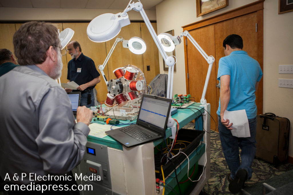
      Look at this picture everybody: energy_science_conf-0010 - A & P Electronic Media

      That is a cart with with about 1500 pounds of batteries! That was one serious job for RS and company to just haul in all that weight. It uses the splitting the positive concept and is just a low tech analog/mechanical method of doing what Peter demonstrated last year at the conference.
      Sincerely,
      Aaron Murakami

      Books & Videos https://emediapress.com
      Conference http://energyscienceconference.com
      RPX & MWO http://vril.io

      Comment


      • Originally posted by Aaron View Post
        Exactly!

        Look at this picture everybody: energy_science_conf-0010 - A & P Electronic Media

        That is a cart with with about 1500 pounds of batteries! That was one serious job for RS and company to just haul in all that weight. It uses the splitting the positive concept and is just a low tech analog/mechanical method of doing what Peter demonstrated last year at the conference.

        I am thrilled to see this progress Aaron. RS is back better than ever.
        Peter L. is on the brink of a new innovation in battery charging tech.

        I don't know what the next phase would be but this one alone is all we
        need to go over the top. Thanks - A - Million for your work
        getting out the message.

        @ Peter
        It is always good to see you rejoicing in success.


        Last edited by BroMikey; 09-01-2017, 07:00 AM.

        Comment


        • Originally posted by Turion
          Just a little history of MY involvement with the 3 Battery system "Splitting the Positive."

          In 2008 I was over at the OU forum:
          David Bowling's Continuous Charging Device

          I had some discussions with folks at Peswiki:
          Directoryavid Bowling's Continuous Charging Device - PESwiki.com

          and did an on air interview with Sterling Allen:

          http://pesn.com/Radio/Free_Energy_No...ousCharger.mp3

          I kept trying to tell people that even WITHOUT the bad battery that got me so excited in the first place, I was getting long runs and restoring batteries that other people were throwing away. But everybody I tried to convince just shouted me down, and I did not have the background (still don't) to argue my points.

          So I gave up.

          I was going through a move to California, a divorce, finding someone new and getting remarried, and that took up my time. I had no time for that stupid free energy crap that nobody would listen to me about anyway.

          Late in 2009 I started a thread here after Luther Goodman contacted me to say he had replicated what I had done on the OU forum and was getting some good results. Sometimes I curse Luther Goodman for that (Not REALLY)

          http://www.energeticforum.com/renewa...erating+System

          At that time I was focused on the "bad battery" but continued to experiment with what the system could do with GOOD batteries. Then Matt joined the party. Some of that work, much of it done by Matt, has never been disclosed.

          But we saw the possibilities and did our best to share what is possible with people on the forum. Or at least we shared SOME of it.

          Shortly after Peter built the setup for last year's conference he and I had a chance to talk about what he had built because that was really the first time Peter had seen what is possible with the 3 Battery setup, even though he knew about it through his work with John B., and talked about it in the Advanced Handbook. But talking about it and SEEING it are two completely different things!

          Matt and I have been yapping about it on the forum since 2009, but nobody listens to us. LOL At that time Peter said, and I still have that email, he thought that the 3 Battery System was possibly the Holy Grail of Free Energy Research. I tend to agree. Once you understand what it can do and how to use it, you simply learn to use energy in a DIFFERENT WAY.

          Inverters and pulse motors are the two MOST IMPORTANT things you can learn to run between the positives, and Bob French could teach folks a thing or twenty about running your solar system in conjunction with a 3 battery system because he has been doing it for quite a while now. Since it was already disclosed at the conference that you can run an inverter between the positives, let me lay out a couple things for you. Break your big battery bank up into two smaller groups. Run the power from your charge controller THROUGH your inverter (to run it) while you are charging up the battery bank, and run a second inverter off of your bank that is already charged up. That is movement of energy from a higher potential to a lower potential, and EVERY TIME energy moves, you can take advantage of it. When the charged up bank gets low, run that inverter between the charge controller and the bank to charge it, while your other inverter is running on the newly charged up bank. Your batteries, minimum, provide you with TWICE the power they did before adding that simple change of a second inverter and where to put it at the right time. Or, you can run the power back and forth between battery banks like the 3 battery system while charging up a fourth bank with solar to inset into the system at some point

          And what I have talked about on this thread, running the motor that drives the generator between the output of the generator coils and the battery bank is ABSOLUTELY the way to run your motor. Alternately, run an INVERTER between the positives that powers an AC motor that runs the generator. That might work too.

          Anyway, that's my history of involvement with this particular topic. It is probably of interest to no one but me, but I have put in the bench time on this system and I know it works. No matter what ANYBODY says. Oh, one thing I REALLY liked about the system that was built in the release of info. It had four batteries instead of three, or rather four BANKS of batteries, because one is always resting. Told ya!!!

          Dave
          I keep taking a picture of your posts

          I remember when you popped in on me and Bob Boyce on OUPOWER
          that website is washed up now that was back 2004. You told me then
          you were working on these motor jobs.

          Let me say something about repeats. As you repeat yourself you find
          out several things. One is if you are board with the story line and two
          if people are catching on. It takes so much time to pass on a new idea.

          I find myself reverting back to old thinking and know it so now I am
          keeping myself from that. The talks that we share together will show
          the answer as to whether each person is trying or not.

          Talks about connecting the inverter in the right place is so easy to
          try and should be used to induce the right thinking. That's been an
          in road for me that kept my focus.

          I can't wait to get my new motor mounted properly. Tonight I worked
          on the drive link CNC bushings and it is true. It is a motor out of a
          dishwasher so I would have to run it off of generator coils that produce
          120vac at 2 amps but then that energy would go right to A battery.

          I like the idea of splitting the positive between two generator coils and
          a single battery. That would be a machine of machines where you could
          connect the device up to the battery and the battery keeps on rising.

          Of course I am no where near that stage. I am happy with getting
          SUUL measuring how much I saved back for the front end while using
          energy at the same time. It is a first step for me and I am excited.
          Last edited by BroMikey; 09-01-2017, 08:15 AM.

          Comment


          • TRYING TO THINK SPLIT POSITIVE

            Everyone should be running the figures on anything they have.
            For instance if I can measure how much power I am running out
            of any power source then connect that thru a device on over to
            a lower voltage or lower impedance, I should be there.

            Here is what I was thinking. Say I had a 117vac wall socket rectified up
            to 155vdc, next I am putting an electric drill motor across the positive
            on over to some batteries to charge up.


            NOT SURE IF THIS IS RIGHT THINKING


            Now we can figure out how much is being used out of the wall after
            rectification, so the source is 155vdc then I could pulse my mixer motor
            or drill motor (And run a rotor with magnets and coils that SUUL) then
            I guess I could charge a bank of batteries that way. I am not sure how
            many batteries in series, however by using the same format suggested
            splitting the positive running a 12vdc device at 24vdc then down to
            a battery bank of 12vdc, we might say 155vdc thru a pulse circuit throttled
            down to 75vdc leaving 75vdc left over to run a set of charge controllers
            in series? Or to 5 batteries in series?

            Just wild thinking, trying to get my head wrapped around this whole thing.


            This message is nothing more than a brain fart, please ignore and finish that coil
            Last edited by BroMikey; 09-01-2017, 07:07 PM.

            Comment


            • Originally posted by Turion
              To convert your AC voltage to what it will be when rectified, multiply it by .636.

              To see what you can run as far as an AC load on your inverter from your D.C. Source, use this tool:
              https://www.batterystuff.com/kb/tool...-inverter.html


              On the testing I have done the AC voltage under load is only a bit more than HALF of the open voltage reading. And then to get DC, multiply that number by .636
              When I hook up my HHO box coming off the AC wall plugs (it is sitting here)
              I get 165vdc if I have a few caps on it. When my brother hooks his HHO
              box up at his house right off the 220vac wall plugs with very few caps
              he gets 310vac.

              When I measure the new washer boards that run 3 phase motors off of
              3 channels of pulsed dc the supply converts 120vac wall power to 165vdc.

              This is my only experience with rectified 120vac. Unless you have a good
              number of capacitors the voltage will drop way down to who knows where.

              To run 5 amps off a rectified welder plug my brother gets 330vac for his
              reading but when he loads it up to 20 amps he has to few capacitors and
              the voltage drops to 310vac or even 300 vac.

              I have looked at the data/formula in the books and get lost with their
              never ending ramblings and thats just how I feel about books.

              I rely on data collected by me just like you do. The key to raising the
              voltage up when you get into a war with amps is to add capacitors.

              Most light loads with an average amount of capacitance usually show me a
              reading of 155vdc. While powering something. So my rule of thumb is if
              I have 120vac then I will get 160dc and then i break that up if I have
              60vac then I will have as much as 80vdc powering very light loads like
              3-7 amps.

              Today my son and I built his first rectifier circuit in class here in our
              home school and his train transformer supply outputs a constant 20vac
              and after the bridge with capacitor his reading today was 28.5vac.

              When he loaded the circuit it dropped slightly, when he loaded the circuit
              heavily the voltage dropped way down to 13vdc and this was because
              he was drawing 1 amp from a 500 ma transformer.

              But normally speaking the voltages should be as I have stated in practical
              application or where ratings are properly arranged so over loaded conditions
              do not prevail.

              In other words, you can over load any circuit.

              I am sure Matt could teach me a thing or two but this is all I know.
              Last edited by BroMikey; 09-02-2017, 02:18 AM.

              Comment


              • Just finished my mount frames on my dishwasher motor so it can
                sit up normal laying on it's side. That is not how they mount in the
                dishwasher. I'll show you all how I did it mainly because these
                dishwashers are everywhere, easy to set up.

                Now i am dialing in my adjustable motor table to the right height and
                next I will probably just stick one of my Variacs on it to lower the R's.
                Gotta start out slow and then raise up the RPM's in a safe manner.

                I have the guard frames ready too plus 1/4" bullet proof plastic sheets
                to cover the frame windows especial right over the rotor area.

                This testing arrangement is only temporary to see where the RMP speed
                up comes and how many strands I'll need for a lower and how many
                for higher RPM's. The scooter motor was fluctuating all over hell ticking
                me off due to bad brushes. It was constantly going up and down in
                speed driving me nuts.

                Once I get my foot in the door to understand where the speeds need to
                be for the number of bifilar strands, I can rework my other motors.

                The coil is good, the rotor is good now all I need is a stable drive motor
                capable of producing speeds of 3000 - 4000 RPMs. I also have a very
                large Variac that plugs into the 120vac wall plug and dials up to 250vac

                This lets me go a little above normal operating parameters but I probably
                won't go that way for fear of wasting power and smoking my windings.

                Comment


                • Hello everyone

                  You all have to see my new motor mount and drive voltages.

                  Split positive goes to Hollywood.


                  https://www.youtube.com/watch?v=NK6AKh-dbfs


                  --------------------------------------------------------------

                  Last edited by BroMikey; 09-03-2017, 01:13 AM.

                  Comment


                  • Mind if I cut in?

                    Hi Dave (Turion,) Bro Mikey, and others
                    Aaron suggested I post the question here that I sent him via e-mail WRT release of RS - Split the Positive. I have spent a good part of the last day or two reading thru a good deal of the posts on this subject, including going back to Dave's posts on OU, so pardon my intrusion here. I bought Peter's Bedini SG series over the last few years, and like RS, and you two, I was very interested in the Split the Positive concept. This year I bought Yaro's Zero Force Motor replication of JB and PL.

                    Please see attached GIF.

                    Rather than the AA's shown, I was using 3.7 volt, 2500 mAH, LiMn batteries and just manually switching them (I have 2 banks of 8 relays and Arduino to automate the process - also have a isolated comparator circuit from previous projects that can measure the voltage on the battery being charged and then the Arduino can change the configuration based on that, or on time, as Peter Lindemann's demo did.)

                    The motor is just a permanent magnet DC motor from a cordless drill. It seemed to have a "kick" back into the two batteries in series, and it (or something) wrecked the one in the bottom left position - actually reversed it so the positive pole was now negative. I got it to flip back to positive is positive with Bedini 1AU charger - but it would never come back up above 1.5 volts.

                    The diode in the negative to negative connection is similar specs to the high speed switching diode that Peter temporarily connected the same way in his Split the Positive - 3 + 1 (the "resting" battery is important) demo.

                    Do I need a diode between the left terminal of the motor and the battery in top left position - to keep radiant or Lenz spikes from coming back into the batteries in series? Do I need to pulse the motor? w/o opening up the motor it seems that the magnets are on the rotor and the the coil(s) are the stator - I don't see any sparks from a commutator. I connected it to another PM motor as generator and was getting a solid 12 volts out of it. The initial test was very encouraging until the one battery reversed.

                    Think I need to punt the LiMn and get a couple more 12 volt 7 AH SLA? (I have 2.)

                    Thanks for your help, your sharing your experience, and all the huge amount of time you have put into this.

                    Jim Morrow
                    Attached Files

                    Comment


                    • Hello Satyam

                      I can't answer many questions right now, out of time. Later.


                      I finally got it

                      Here is my latest success on my new test bed for a Tesla patent
                      to go lenz free regenx Speed up Under Load or Acceleration under a
                      load.
                      The new speeds are incredible at over 2800 rpm's, I only need 8 strands
                      instead of 18 strands to reach just above the null point. It is really smooth
                      so i am going to reach behind my back and give it a pat.

                      Watch the meters.


                      --------------------------------------------------------------

                      https://www.youtube.com/watch?v=kT-nJr0rMmY

                      ---------------------------------------------------------------

                      https://www.youtube.com/watch?v=MIWIytKpk3Q

                      ---------------------------------------------------------------

                      Comment


                      • HI Jim,

                        Great work.

                        Would you mind sharing this isolated comparator circuit and Arduino configuration?

                        Kind regards,
                        Ray

                        Comment


                        • Two Uploads Coming

                          Two more testing video files for load testing as well as (SUUL) regenrative
                          (AUL) acceleration under a load via Tesla patent for BIFILAR COILS that
                          produce power and are lenz free.

                          This is my first lenz free coil, it generates power while assisting the rotors
                          motoring action. Got a hell-of-a-zap at 600 plus volts on very low ma.

                          Watch me in my new video show continued tests proving Tesla right. Oh
                          and many thanks to Dave, John Bedini, peter L. and so so many others
                          who have helped me to get to this point.

                          Part Two

                          In Pt 2 I smoked a neon in 10 seconds that has a resistor on it also. It ran
                          at 500 volts for 3 seconds and then when the resistor and bulb degraded it
                          ran at 220volts. It is a neon that runs at 110volts.

                          That zap I got running a 1/8" air gap was somewhat painful at 650 volts at
                          around 30ma. or 20 watts of power WOW WEE.

                          The motor drive is out of a common dishwasher variac setting 90 volts
                          at 1.80 amps = 162 watts. I will get three amounts of generated power
                          of 20 watts so potentially 60 watts for the 24 strand coil.

                          Again this is only ballpark figuring, probably way off.

                          If it were true that I could utilize 670 volts at 30ma and each coil did
                          produce a max of 670 volts 90ma, then 3 "C" Core type coils would
                          generate a total of 180 watts.

                          https://youtu.be/n7wto50-5dU

                          Last edited by BroMikey; 09-04-2017, 06:32 AM.

                          Comment


                          • Iso-comparator circuit

                            Originally posted by Majestic81 View Post
                            HI Jim,

                            Great work.

                            Would you mind sharing this isolated comparator circuit and Arduino configuration?

                            Kind regards,
                            Ray
                            Thanks Ray,
                            I haven't done anything with the Arduino UNO or relays just yet. The UNO looks more than capable, but I need to solve the basic problems and know what I need the Arduino to do before I start writing a sketch for it.

                            I will look in old Dell P4 Windoze XP for the iso-comparator circuits and post them later tonight or tomorrow.
                            Jim

                            Found it - attached.
                            Attached Files
                            Last edited by Satyam108; 09-04-2017, 04:31 AM. Reason: attach jpg

                            Comment


                            • Thanks Turion

                              Originally posted by Turion
                              Jim,
                              I have been running this circuit for over ten years now with a huge variety of different motors and batteries and I have NEVER seen any battery reverse polarity. Of course I have never put a diode where you have one either.

                              If you have read what Matt spent a lot of time explaining about this circuit with the use of the boost module, he explains that you have to look at the motor as the dividing point or balance point. On one side of the motor you have 24 volts and on the other side you have 12, so those two things attempt to equalize and the energy moves. On the other side of the motor you have the output of the motor plus the 12 volts, and that energy is moving up the negative into the two primary batteries. Using Matt's modified motor and the boost module, the output is a bit greater than the 24 volts in the primaries, so you get a bit of charging of the primaries down the negative side.

                              If that same principle holds true with what you have, perhaps that particular motor is producing huge spikes of negative that overwhelm the 12 volts in battery three with out affecting it (for whatever reason) and are hitting the primary battery to flip it. I really don't know, but I have two suggestions. First, flip the motor wires. It will reverse its direction of run and MAY affect the direction of output of the negative. The other, and easiest solution, is just remove that diode. I have never used one in that circuit ever.
                              Peter L put a similar diode in the negative line in same direction and it sped up the SG motor energizer. Dramatically increased charging pulses on the single battery being charged. He removed it after a few minutes because the SG kept accelerating - you can actually hear it in the video. So I tried to run before I could walk with this maybe. Going for the homer instead of just trying to get on base. HA!

                              I will take your suggestions - remove the diode first and see what happens. Record voltages, etc. Try reversing the motor connections to see if that makes any difference.

                              Perhaps I just got a bad LiMn battery and a couple of the cells in it flipped and I only got one to unflip? In one of your posts I remember you writing that the single battery that is being charged needs to be "dead' or majorly discharged before we start this up. Do you still think so?

                              Not ready to wade into boost modules or rewiring motors just yet. If JB got this to work in '84 with just a simple motor - then gotta replicate that before getting more complex.

                              Thanks for your help.
                              Jim
                              Attached Files

                              Comment


                              • Part 2 Test bed hands on results.

                                Split the Pos........Regen Accel speed up coils, thx Tesla.


                                https://youtu.be/7lBDW-yvDsM

                                Comment

                                Working...
                                X