Announcement

Collapse
No announcement yet.

Splitting The Positive

Collapse
X
 
  • Filter
  • Time
  • Show
Clear All
new posts

  • Originally posted by Turion
    The post this was taken from is 8 years old or older. Please do NOT contact Amir at this time. He's a busy man!!!

    I reposted this for several reasons from 2012? It is in the 3 battery
    thread and shows the level of seriousness about what you have invented.

    I am sure if others wanted to patent their own devices they might not
    want to go to a California Lawyer but maybe go where they can set
    down in person and talk.

    The other reason is that it shows how hard you were working on things
    and how far you have come since then. What caught my eye was your
    work with the inverters instead of the motors.

    I am still hunting down posts like this from 2012 or before if I can find
    anything on inverters running in place of the mod mtr. I think it important
    that people realize that an inverter can give the experimenter great
    results, not like my recent trial runs.

    I didn't realize the significance of having the exact voltages as show til
    this week. I mean charge both ends? It didn't seem real so i went looking
    for more posts. I don't think anyone here will be patenting until they can
    learn how it works first.

    But it is nice to know someone can get extra and is trying to get an
    invention thru the law offices. 5 years is a long time for a lawyer who
    may be thinking of retiring by now.


    PS I REMOVED THE NUMBERS
    Last edited by BroMikey; 11-21-2017, 05:38 AM.

    Comment


    • Playing Catch up

      3 BATTERY CHRONICLES


      I may not understand it all yet but these are very interesting.


      Originally posted by Turion View Post
      You don't have to worry about Matt's motor running hot unless you are stacking up some batteries in position one and two. He is running it at 120 volts, not 12, so at that high voltage you have to make sure the voltage the motor produces has somewhere to go QUICKLY or it will back up in the wiring and overheat the motor. A battery won't absorb it fast enough, so you need to use some caps in parallel. If you are just running the 3BGS setup you should be fine. Matt and I and some others are exploring some limits with this setup and with this modified motor, so we are doing some things that call for some extra circuits. If they prove out, you'll read about them here.


      Dave
      Originally posted by Matthew Jones View Post
      The motor has too turn clockwise as you face the shaft end. If it isn't your not going to get anything out of it.
      Remember it moves slow with low voltage. Thats for reason, so you can see what your doing. It will speed up with higher voltages but you have to have a recovery system in place or you'll burn up.
      I had mine running on 140 +- volt at 19000 rpms. No heat and no spark. No consumption...

      Be careful

      Matt
      Originally posted by Turion View Post
      wantomake,
      Thanks for posting that video. Pretty cool.

      Yeah, the goal is to figure out how to get battery 3 to hold at that point where the energy comes flooding into it. The very first setup I ever had did that and I didn't have any idea how lucky I was. I ran every kind of load you could imagine. Lights, drills, my shop vac, a 12 volt car vacuum, fans, and all sorts of small motors. You could try running your motor at the same time and adding small loads to the motor. You could run another motor shaft coupled as a generator and rectify the output to run 12 volt devices. If you can get them to balance with each other, the voltage on battery three will remain steady.

      OR you could just leave it alone and let it continue to go up and down like it is doing. It may do that FOREVER, and that would surely convince some folks (when the thing is still powering those lights in a few days) that there is somethng to this thing.

      https://pesn.com/archive/2013/01/14/9602264_Bowling_Effect--Two_good_and_one_bad_battery_power_a_motor_while_r echarging/index.html


      Originally posted by Turion View Post
      My wife always tells me that the more "wrong" I am about something, the louder I talk, as if the volume of my voice will convince her even though I KNOW I'm wrong. And she is right. We laugh about it all the time. So it is with the people spouting misinformation. They try to roll over us with the volume and the quantity. I would rather listen to the quality of the words.

      I couldn't sleep this morning so as I made the wife coffee, I was pondering the 3BGS and thought I would share something. I have repeated the story many times of how, when my original device "came to life" after 15 minutes, I immediately put a meter on battery three. What I saw was that it would read 24 volts, go slowly down to 18 IN JUST A MATTER OF MINUTES, at which point the motor would start, and it would continue to run as the voltage continued to drop down to around 8 or 9 volts, at which point the motor would shut off. The voltage would immediately jump to 24 volts and the process would repeat over and over. I have said before that I thought this meter was reading not the voltage IN battery 3, but because of the way the setup is wired, it was reading the POTENTIAL DIFFERENCE between battery 3 and the two primaries wired in series.

      Think about that for a moment. When the meter is reading 24 volts, it means battery 3 is basically DEAD. Within minutes the meter drops to 18 volts, which means there is about 6 volts in battery 3, and this is enough to complete the circuit and provide the power for the motor to run so it starts up. The voltage in battery 3 continues to climb which makes the reading on the meter go down, and when it gets to 8 or 9 volts, the POTENTIAL DIFFERENCE has now dropped to 6 volts, which is not enough to run the motor and it shuts off. The voltage immediately jumps to 24 volts, and the cycle repeats.

      What does this tell us about battery 3 if my theory is correct?

      1. First, the original battery 3 would NOT hold a charge.
      2. The system is capable of putting a FULL charge into the battery in a matter of minutes. I have only told a few folks the following story because it sounds too unbelievable, but I took this setup (when it was working perfectly) out to my dad's house. He is off the grid on a solar system and has a huge battery bank. That battery bank was way down when I arrived early in the morning, and we hooked in the 3BGS battery 3 in parallel with his battery bank. It charged his entire bank in a matter of minutes, something that would have taken HOURS to do with his solar setup.
      3. The minute the motor quit, the voltage on battery 3 dropped like a rock. Or the meter would not immediately have read 24 volts again.
      4. The battery obviously TOOK a charge, because that potential difference dropped to 18 and then down to 8 or 9 volts. (Which would mean battery 3 was at a charge of 14 or 15 volts, if my theory is correct.)

      I think this gives us important information about what battery 3 needs to be capable of doing in order for us to find a substitute for it. Unfortunately, I agree with Duncan, that finding a perfect battery three is a matter of luck. We could try forever, and then when you get one, the system will fix it.

      Dave
      Originally posted by Turion View Post
      OK, as to a precis for new folks.

      The setup is exactly what it has always been. Connect two good batteries in series and then reverse the third "bad" battery and connect it. Depending on which end of the series batteries you connect the bad third battery to, you either have two positives left to connect your motor to, or two negatives. My original motor was connected between the two positives, but I have had lots of success connecting a brushed dc motor between the two negatives. We're not sure it makes a difference. But it DOES make a difference which direction your motor rotates. Switch the wires on the motor and you will see it runs faster one way over the other.

      Things we do know.
      1. Increasing the resistance between the poles of the bad battery lengthens the run times before the primaries began to discharge.
      A. Connecting large resistors between the poles of the primaries seems to help accomplish this.
      B. Changes in the electrolyte can accomplish this.
      C. Drying out the battery somewhat can accomplish this
      2. A battery that WON'T hold a charge is the very best battery you can use in the 3rd position.Most batteries will accept a charge, but some, for whatever reason, won't hold it. These work the best.

      3. You can get many of the same effects we get with a bad battery by using a capacitor in the third position, but you will almost always lose voltage in your primaries.

      4. If you do short runs and pulse the motor, the primaries can completely recover and in some cases gain voltage.

      5. With some setups the primaries gain voltage.

      6. With some setups the batteries ice up or turn cold.

      7. A dc motor or a pulse motor output more voltage than is input in the 3BGS configuration.

      8. All three batteries should be the same kind, i.e. flooded lead acid or AGM.

      9. The more you can figure out ways to PULSE the system the longer you can go without primaries discharging.

      10. When you use a standard motor and you get the system in the zone ( balanced loads---see post #1) the more torque it has.

      If you want tech aspects of what people have seen on their scopes and meters, you will have to read the posts. I'm not going back through all these pages to spoon feed anybody either. It is posted. It is here. If you care enough you will find it. You will read LOTS of examples of folks who have seen successes with this. And some folks who have seen nothing because they didn't have the right bad battery, which I have always said is the "key."

      David
      Now i think instead of a bad battery that is slightly shorted and draining
      out power all of the time a small load works as well.

      Originally posted by Turion View Post
      .............this thing can be hell on inverters. I have burnt up some expensive ones! Having said that, my original setup did use an inverter. I was brand new to this stuff, so I took no real measurements whatsoever. I balanced the loads on the inverter by torquing down on a pulley arrangement I had connected to the motor which made it harder for the motor to turn. This was hard on the rubber belt. I ran a shop vac, a lamp and an electric drill all at the same time, but how many watts or amps that pulled, I could't tell you. I ran these devices and several others (there were only three plugs on the inverter) for most of a day and for several days in a row and the primaries went up so high in voltage(one of those days...17 or 18 volts) that we got scared and ran out of the room.

      On another occasion I also connected the thing to my dad's bank of 6 volt (wired in pairs for 12 volts, and then wired in series) battery bank which was dead and charged the entire bank in less than a half hour.

      Those are examples of the power this thing puts out.

      That was then, and this is now. Here at the house I have a light board with a row of bulbs that are AC, and a row of bulbs that are DC all connected to switches. I have run a motor attached to the shaft of the Razor Scooter motor as generator through a full wave bridge to the DC bulbs, and connected an inverter to battery 3 to run the AC bulbs. AT times I have had 65 watts on the AC side balanced with 150 watts on the DC side for quite a while. There HAVE been times when the AC side was up over 300 watts, but that was hard to balance and it would not run long before the inverter shut it off. That still really doesn't give you any direct measurement of what the setup was putting out, but on these occasions the primary batteries either went up in voltage slightly, or went down slightly but regained their original charge (or higher) after resting.

      Dave
      Last edited by BroMikey; 11-21-2017, 11:37 PM.

      Comment


      • The new $8 meters are in and are awesome devices. Here is how
        you connect them.


        Comment


        • Boost Converter Coming Soon


          I have the watt meters, I don't have any boost converters so i hit
          the button again and will try these. Since I am not working with the mod mtr
          I need a circuit that will stop and not go over 14.8vdc which any
          higher will smoke your inverter. You need to drive the inverter at a specific
          voltage.

          The 3 battery split positive differential voltages go up and down on their
          own starting at 15.2v down to where the inverter fails. The inverter can
          take 14.50v and you need 2volts more than what is in the battery so if
          you are starting with a dead battery around 12v it will hit 12.5v soon,
          you will be about right.

          The second booster is recommended for the motor experiment.

          I will verify the correct waveform needed when running this setup.
          However just any booster and just any inverter may not work at all.

          I hope all goes well for each of you. If you are a teenager you will be able
          to make these tests.


          Last edited by BroMikey; 11-23-2017, 02:07 AM.

          Comment


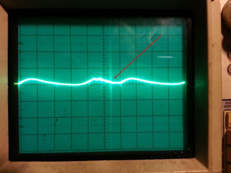
          • Modified motor and 3 battery generating systems wave shape
            with spike. So if you are not using the mtr but instead an inverter it
            has been suggested you may want to look for these actions on a
            scope (if you have one) when making small adjustments on your boost
            converter. Otherwise make fine adjustments and wait to see if voltages
            increase on either battery pack or both.


            The scalar is not the same as a transient. Transients are
            formed from particle compression around the magnetic field. So.. the
            mag field inflates out and around the coil. All the particles around
            that coil are attracted to the field and they compress each other
            into a dense mass. Both field expanding and the particle racing in.
            This mass then collapses following the field into the coil and cutting
            flux of coil, resulting in charge.

            A scalar is caused from compression in iron not in the environment.
            Think about the motor. It has coils of the same polarity pointing in
            opposite direction. Every time any of the coils are fired you get an
            opposing force. The commutator runs out before anything can get
            released (unless you use the timing circuit). Now we have the
            energy stored in the iron. Once the commutator opens back up
            the power in the coils goes opposite. This pushes the stored
            energy in the iron out in every direction.

            The energy coming out has no polarity. It has No time factor and
            what you are able to see on the scope has no current. It grows
            through resistance (Not a resistor though).
            And you cannot filter it in half. But caps love them.
            Last edited by BroMikey; 11-23-2017, 09:15 AM.

            Comment


            • Setting up batteries for the next split positive runs.

              https://youtu.be/HkzGn9iPNR4

              Comment


              • Differential Loading

                Split Positive Differential Loading in the C/20 rate.

                I am learning the light metering functions on the camera, also a new
                stand to get the picture more clear plus using the class room HQ setting
                then putting it to a video cruncher to lower upload time. I have won this
                war as of today, I apologize for some of my past recent video quality.

                This shows the basic differential voltages and what happens when you
                do it wrong as well as doing it correctly. These batteries run $1200 dollars
                for what you see on the desk. The rest of the circuitry is popcorn peanut.


                https://youtu.be/8FSBHXtXkAE


                -------------------------------------------------------------------

                Comment


                • Hi Bro
                  Good to see you are advancing with Dave's and Matt's setup. I thought you had done that ages ago.
                  Just want to tell you that if you keep connecting batteries in parallel this way in the long term you are going to destroy the one(s) that is actually connected. You have to draw current evenly from all parallels. So all the wires should have the same length and thickness of course. For four batteries setup in parallel here is the best setup.
                  Attached Files

                  Comment


                  • Originally posted by liber63 View Post
                    Hi Bro
                    Good to see you are advancing with Dave's and Matt's setup. I thought you had done that ages ago.
                    Just want to tell you that if you keep connecting batteries in parallel this way in the long term you are going to destroy the one(s) that is actually connected. You have to draw current evenly from all parallels. So all the wires should have the same length and thickness of course. For four batteries setup in parallel here is the best setup.
                    Thanks again Liberal63

                    I think I hear this somewhere and I'll keep it in mind if I decide to use
                    them at higher amp rates. Each battery can do short runs of 20 amps. The
                    manufacturer states that each battery has a low internal resistance
                    making it possible to run 10 amps without much heating.

                    My experiment only takes 180ma to run and each row of 4 parallel batteries
                    is capable of 40A-80A however if a person sticks to the C/20 rating with
                    each battery a 16ah this would be 16 X 4 =64ah / 20hrs.

                    64ah divided by 20 hours = 64,000 divided by 20 = 3200ma

                    In most of the applications that a regular guy would use these batteries
                    if often based on how much money one has. these 12 batteries cost
                    over $100 a piece making this test bed $1200 just for the lead packs.

                    So this means that each battery can only deliver 800ma each hr over a
                    20hr period for a true C/20 rate. Any more of an amp draw starts to
                    cause small amounts of heating on the lead plate and this lowers the
                    batteries ability to get back what was put in it.

                    Even a tail light on a car pulls over 1 amp at 12volts.

                    Each bus bar that carries the current from one battery to the next one
                    is capable of 200 amps each. It would be like driving a gokart on a 200 lane hwy at 800ma.
                    What you are seeing is how commercial installations
                    connect their hundred thousand dollar back up packs and is an excepted
                    standard.

                    No I have never done this experiment using an invert with the right
                    booster and new batteries. Stay tuned, I have not completed this
                    experiment yet.

                    The 100 watt light bulb test is only to show battery voltages and let
                    the viewers see the batteries capability at C/7 rates and is only for
                    a few seconds.


                    Last edited by BroMikey; 11-26-2017, 08:34 PM.

                    Comment


                    • Modified Pulse Motor Battery Conditioning

                      My battery pack is being hit with special pulses and sharp spikes.
                      I ran down the charging pack to 10.40v and after 11hr it has charged up
                      some.

                      The run packs seem to just hang in one spot forever and when i connect
                      a resistive load load of 900ma at 12.90v (Differential run volts) the run
                      pack go down much quicker. That is a first step and I for one am glad
                      I found you guys.

                      Yes i have heard all of the reverb, just regular guys who are finally
                      showing us your real personality. That is what I am looking for, not the
                      phony put on stuff

                      Talk to me fella's


                      https://youtu.be/HT09vkfJQc4


                      Comment


                      • Okay here is the latest. Numeral Uno I am not going to try and prove
                        anything, plain and simple when I disconnect the Mod Mtr and connect
                        other loads the voltage on the run pack begins a more rapid descent.

                        This experiment is the beginners steps to conditioning batteries and to
                        see if I can get a lot of charge up's for the charge pack off the initial
                        charge sitting on the run pack. After over 15hrs the run pack is 24.8v
                        and the charge pack is 12.22v

                        I can hook up a scope to tweak the back plate yet it makes no difference
                        to the mod mtr abilities. Once I get the 4 boosters in the mail the fun
                        begins. What it looks like to me is that I am going to end up with a
                        charging station that will take weeks to go down. That is a bunch better
                        than a few days.

                        The old load figures were 6.2w and each battery held 210wh so go
                        do the math. Now I am running 11.6w load.

                        Each battery

                        210wh X 4 = 840 wh per 12v section which is 4 times the capacity
                        but loading double (Approx) so run times should be double from a
                        conventional baseline test.

                        Comment


                        • People do not realize that the power of life and death is in their
                          tongues and once you have killed people with words you can not
                          fix the broken lines. All they can do is break it again.

                          Each exchange shows many things, the point of no return is here for
                          some. On the other hand we can not stop learning because of a few
                          sore azz devils are all upset

                          The "Splitting the Positive" thread is an animal, all to itself, with none
                          other than yours truly as guide. The modified motor is an energizer for
                          batteries leaving us with a hopeful COP of 1 which is great when you
                          understand that you are getting a 25 percent additional mechanical
                          energy out. Sound familiar? Yup that is because John Bedini led the
                          way with this tech since the 70's using two positive poles to charge
                          his batteries.

                          In this version of an energizer made with an off the shelf scooter frame
                          having 2 north poles (sound familiar) is run between positive battery
                          poles and charging at the same time. This is the next step in the evolution
                          of using recirculated energy.

                          Now to confirm the COP value of the basic mod mtr running between
                          positives. This is a very important first step that may seem insignificant
                          to some that if you miss, may not be able to grasp the next steps that
                          will lead to COP 3 and 4 systems and on up.

                          Remember what John bedini's best energizers did, they ran off of run
                          batteries that the motor kept charging in the back stroke of spikes
                          as the charging batteries went right up. COP 1


                          https://youtu.be/EVk19xje7Xs


                          Last edited by BroMikey; 11-28-2017, 08:02 AM.

                          Comment


                          • Originally posted by BroMikey View Post
                            [B]
                            The modified motor is an energizer for
                            batteries leaving us with a hopeful COP of 1 which is great when you
                            understand that you are getting a 25 percent additional mechanical
                            energy out
                            .

                            Hello Bro

                            I'm a beginner in this area. Just a question. ( @ COP 1) You say; you are getting a 25 percent
                            additional mechanical energy out
                            I can't understand more than that you only have these 25 percent additional mechanical energy out in the form of delivered internal motor losses, heat to the bearings and slipring friction loss when the motor is spinning. Or do you, can you?, load the motor shaft with something also a generator, or a saw e.g. an still have a COP=1 situation to the batterys?

                            Regards / Arne
                            Last edited by seaad; 11-28-2017, 11:07 AM.

                            Comment


                            • Originally posted by seaad View Post
                              Hello Bro

                              I'm a beginner in this area. Just a question. ( @ COP 1) You say; you are getting a 25 percent[/SIZE] additional mechanical energy out
                              I can't understand more than that you only have these 25 percent additional mechanical energy out in the form of delivered internal motor losses, heat to the bearings and slipring friction loss when the motor is spinning. Or do you, can you?, load the motor shaft with something also a generator, or a saw e.g. an still have a COP=1 situation to the batterys?

                              Regards / Arne
                              Hi Arne

                              I am in the process of verifying MY MOD MTR ENERGIZER this means I
                              have not collected all of the data for mine. Mine is different from every
                              one else's because i used what I had on hand, 20awg wire.

                              My bearings need replaced also but it runs slow and there is no heat.
                              John Bedini said that his energizer can give a COP of 1 and still have
                              20 some percent mechanical left over. This fact was repeated in the
                              3 battery thread as well as the basic free energy device thread.

                              The Mod Mtr is an energizer and all by itself does many great things to
                              a battery, plus i for one would never built a 12 pole monopole motor but
                              this little guy I would. He got me on that one. The Mod Mtr is factory
                              precision tolerance very compact. It cleans plates well, just for openers.

                              Lets face it, one of the biggest problems with modern day systems using
                              a battery is that it runs down on loads til the sulfation creeps up the
                              plates and chokes off the reservoir. This is happening ever single
                              micro-second and that process does not take a long period of time.

                              Thanks for commenting SEAAD it is guys like you with an open mind that
                              keep me trying to share what i have learned and what my experiment
                              is teaching.

                              For example:

                              Today after more than 14 hrs of running my little LED light bulb the
                              voltages read as follows:

                              Under load 11.67v

                              No load after 10 min resting =11.75v

                              160wh of usage so far.

                              The pack I am getting energy out of when i run the ModMtr is sitting
                              at 25.1v and very soon will be back generating. My boosters are not here
                              and with Xmas on the way they may never come even tho I ordered
                              them weeks ago.

                              Also for the attentive adepts: Notation:

                              These batteries are in need of more cycles to get them peculating with
                              perfection, you guys know what I am talking about. You are the ones
                              who sat on a meter like a hen waiting for the chicken to hatch.

                              Forget the idea of Mikey giving up.

                              I know batteries of all kinds well and these stinky plates are giving off
                              that crusty dull lead odor with the first cycles and not the fresh smell
                              like well conditioned batteries have.

                              The data is coming in and I'll probably do a short video when i shift into
                              generating again. BRB


                              PS Never mind that man behind the curtain trying to tell you that you
                              can't think for yourselves, how insulting, as if you can't think on your
                              own.

                              There is only DO!!

                              Comment


                              • Let me get back to the generating systems

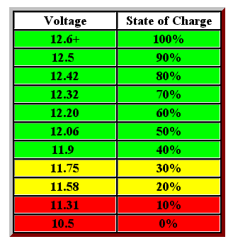
                                Here is a chart for a 12v battery percent charged.


                                What i am learning is that a 12v battery not fully charged does not
                                always give 100% of the read voltage but if you wait 30 minutes
                                after you connect the loads then read the voltage, you may have
                                a better reading.

                                Using this approach my pack under load the first 30 min dropped to
                                12.08 volts, this is close to a half of a battery and now after 14 plus
                                hrs of runtime still have 30% left.

                                Running figures it looks like we will get very close to the 400 plus watt
                                hours i had thought should be available on this first discharge. Once
                                the battery pack is really dead (Very bad for lead batteries) I can go
                                back to generating with greater charging ability due to the increased
                                differential required.


                                My old 1970's block transformer trickle charger open voltage reads
                                19vdc and under load charging at 2 amps then quickly to 1.5amps
                                is holding a higher potential over the battery plates to get energy
                                to move, somewhere around 14volts.

                                It has been stated that you need to hold a potential difference of
                                2.5v over the battery voltage. This number is 14.5vdc for efficient
                                charging to take place and not keep batteries so low of a charge
                                they get ruined.

                                This is why a booster is the next step in the experiment. Taking batteries
                                down low is not always bad as long as you don't leave them discharged.
                                Reverse chaging is part of battery maintenance and first requires that a
                                battery is discharged below 1v.

                                If you are doing experiments with batteries that can not sustain a reverse
                                charging cycling without failing then your experimental data my become
                                inaccurate due to internal shifts accompanied with degraded plates.

                                Or it may be that you do not have true deep cycles.

                                https://www.youtube.com/watch?v=LX_o3hl2Dv4


                                https://www.youtube.com/watch?v=3LzcGXHjpdM


                                Lifepo4 batteries at 3.2v coupled with some supercaps seems like a
                                great alternative for those who already have bikes running on these.


                                PS Never mind that man behind the curtain telling you to kneel in
                                his presence, he must build new walls to protect his empire.
                                Last edited by BroMikey; 11-28-2017, 09:34 PM.

                                Comment

                                Working...
                                X