Announcement

Collapse
No announcement yet.

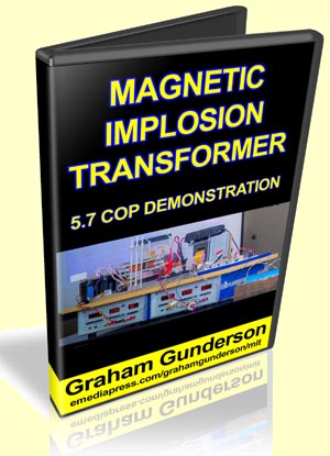
Magnetic Implosion Transformer by Graham Gunderson

Collapse
X
 
  • Filter
  • Time
  • Show
Clear All
new posts

  • Magnetic Implosion Transformer by Graham Gunderson


    So many people want to see overunity demonstrations and at the Energy Science & Technology Conferences, you get to see live overunity demonstrations and this has been the case at almost every conference for the last 5 years.

    This year, Graham Gunderson showed the Magnetic Implosion Transformer that he invented and it measured out at 570% more output than the input he paid for!

    Get your copy here: Magnetic Implosion Transformer by Graham Gunderson

    As a matter of fact, he can dial the input down until it goes negative, which means the COP (coefficient of performance) is infinite! Coefficient is the ratio between desired work done in a system compared to the work that we have to pay for.

    Graham is one of the few experts in actually knowing how to properly measure input versus output in these kind of devices who actually has developed his own overunity technologies and this is one of the most astounding!

    Get your copy here: Magnetic Implosion Transformer by Graham Gunderson

    In his presentation, he actually includes some of the details that he originally thought about keeping secret, but he shared them with the entire audience anyway and you now have an opportunity to hear it yourself.
    Sincerely,
    Aaron Murakami

    Books & Videos https://emediapress.com
    Conference http://energyscienceconference.com
    RPX & MWO http://vril.io

  • #2
    Is there enough info in the video to make a realistic attempt at replication?

    It's just not worth the time and money to put into something that is not practical. I just want some real info and full disclosure on something that works. Or is there some "secret" info that makes it just an interesting video that people have no realistic chance to figure out while trying to make ends meet?

    Sorry, not trying to sound negative but I just can't spend money on things that are not practical for a person to be reasonably able to reproduce.

    Thanks.

    Comment


    • #3
      Originally posted by SilverToGold View Post
      Is there enough info in the video to make a realistic attempt at replication?

      It's just not worth the time and money to put into something that is not practical. I just want some real info and full disclosure on something that works. Or is there some "secret" info that makes it just an interesting video that people have no realistic chance to figure out while trying to make ends meet?

      Sorry, not trying to sound negative but I just can't spend money on things that are not practical for a person to be reasonably able to reproduce.

      Thanks.
      Dear SilverToGold

      You are not being negative just practical.

      There is not enough information in the video to build a device directly. There are no drawings, parts lists, wiring diagrams, or testing protocol. If there were, this would be a 10 hour video or a 300 page book with at least 50 drawings and charts.

      A serious researcher is looking at about $1,500 to $3,000 to reproduce this construction. Then they will have to have at least $5,000 in instrumentation to be able to accurately measure its performance. Even if it does work well it will produce only 10 watts of power and still need to be plugged into the wall.

      This is not a hobby construction project like putting together a model airplane or toy car. This is serious basic science that is knocking on the door of a potential technical breakthrough, maybe even an age changing technology in its infant form.

      Even if this machine does prove to meet or exceed the observed performance measures it will take years before you can buy one of these at Wall Mart to power your toaster, providing that the MIB doesn't snatch it first.

      If you are a serious self funded garage scientist who has been looking for some foundation of a possible Over Unity device then this video is for you.

      The important thing is that this apparatus can be built in a garage and is within the means of many people doing this kind of work. Perhaps, in time, simpler and cheaper approaches can come of this, however not at the moment. Stay tuned, maybe some fast progress will be made and in a year or so you can build something from a kit for say $200 that will charge your cell phone, but don't hold me to that schedule.

      Thanks for your interest and bringing up these important points.

      Spokane1

      Comment


      • #4
        replication

        Originally posted by SilverToGold View Post
        Is there enough info in the video to make a realistic attempt at replication?

        It's just not worth the time and money to put into something that is not practical. I just want some real info and full disclosure on something that works. Or is there some "secret" info that makes it just an interesting video that people have no realistic chance to figure out while trying to make ends meet?

        Sorry, not trying to sound negative but I just can't spend money on things that are not practical for a person to be reasonably able to reproduce.

        Thanks.
        In addition to what Mark already said, Graham may be sharing the diagram and we may make pre-made modules available to help make it easier for builders to get results. That being said, they may be available to those that actually purchased the presentation to support the work.
        Sincerely,
        Aaron Murakami

        Books & Videos https://emediapress.com
        Conference http://energyscienceconference.com
        RPX & MWO http://vril.io

        Comment


        • #5
          Thank you gentlemen, I appreciate the input. The thing that kind of makes me hesitant is that if I heard correctly, even Graham says he does not really understand how it works - so that is a big question for me. If one does not understand the underlying theory, it is going to be very hard to make something work. I'm not looking for an "easy" solution, I would just like to have a practical basis to build from. That is why I like the Bedini's series that is offered, it makes sense.

          Again, thanks for the input and I hope Graham has much success in his research.

          Comment


          • #6
            Hello

            I guess I forgot where to find this information. Somewhere in these
            threads the basic working principle of the implosion transformer
            should be available.

            Is there a working replication or a video of it running? Did the info
            get out to where a working model could be made by other experimenters?

            I still have no idea of how that device operates.

            Thanks in advance.

            Comment


            • #7
              Basic Layout Here

              I found a basic layout of the way this works. Starting from the
              beginning you can see what it is all about, even if you had no
              intentions of building a 10kw unit. plain and simple.

              Thx REX


              http://www.rexresearch.com/gunderson/gunderson.html


              Solid state electric generator
              US7830065


              A solid-state electrical generator including at least one
              permanent magnet, magnetically coupled to a
              ferromagnetic core
              provided with at least one hole penetrating its volume; the hole(s)
              and magnet(s) being placed such that the hole(s) penetrating the ferromagnetic core's volume intercept flux from the permanent
              magnet(s) coupled into the
              ferromagnetic core. A first wire coil is
              wound around the
              ferromagnetic core for the purpose of moving the
              coupled permanent magnet flux within the ferromagnetic core. A second
              wire is routed through the hole(s) penetrating the volume of the ferromagnetic core, for the purpose of intercepting this moving magnetic
              flux, thereby inducing an output electromotive force.; A changing
              voltage applied to the first wire coil causes coupled permanent magnet
              flux to move within the core relative to the hole(s) penetrating the core volume, thus inducing electromotive force along wire(s) passing through
              the hole(s) in the ferromagnetic core. The mechanical action of an
              electrical generator is thereby synthesized without use of moving
              parts.


              BACKGROUND OF THE INVENTION

              1. Field of the Invention

              This invention relates to a method and device for generating
              electrical power using solid state means.


              2. Description of the Related Art

              It has long been known that moving a magnetic field across a wire
              will generate an electromotive force (EMF), or voltage, along the wire.
              When this wire is connected in an electrical closed circuit, in order
              to perform work, an electric current is driven through this closed
              circuit by the induced electromotive force.

              It has also long been known that this resulting electric current causes
              the closed circuit to become encircled with a secondary, induced
              magnetic field, whose polarity opposes the primary magnetic field that
              first induced the EMF. This magnetic opposition creates mutual repulsion
              as a moving magnet moves toward such a closed circuit and attraction
              as that moving magnet then moves away from the closed circuit. Both
              these actions tend to slow, or “drag” the progress of the moving magnet generating the EMF, causing the electric generator to act as a magnetic brake, in direct proportion to the amount of electric current produced.

              Gas engines, hydroelectric dams and steam-fed turbines have historically
              been used to overcome this magnetic braking action occurring within mechanical electric generators. A large amount of mechanical power is ultimately required to produce a large amount of electrical power, since
              the magnetic braking interaction resulting from induced electrical
              current is generally proportional to the amount of power being
              generated.

              There has been a long felt need for a generator which reduces this well-known magnetic braking interaction, while nevertheless generating
              useful electric power. When the magnetic fields within a generator are
              caused to move and interact efficiently electric power can be supplied
              with far greater economy. Improving power generating and conversion efficiencies also increases the power capability of a device thereby,
              inter alia, providing a mechanism to reduce the size and weight of the generating device. Smaller and higher power density devices are
              particularly useful in applications such as aviation, automotive, and
              portable electronics including hand held devices.


              SUMMARY OF THE INVENTION

              It has long been known that the source of the magnetism within a
              permanent magnet is a spinning electric current within ferromagnetic
              atoms of certain elements, persisting indefinitely in accord with
              well-defined quantum rules. This atomic current encircles each atom,
              thereby causing each atom to emit a magnetic field, as a miniature electromagnet.

              This atomic current does not exist in magnets alone. It also exists in
              ordinary metallic iron, and in any element or metallic alloy that can be “magnetized”, that is, exhibits ferromagnetism. All ferromagnetic atoms
              and “magnetic metals” contain such quantum atomic electromagnets.

              In specific ferromagnetic materials, the orientation axis of each
              atomic electromagnet is flexible. The orientation of magnetic flux within,
              as well as external to the material, easily pivots. Such materials are
              referred to as magnetically “soft”, due to this magnetic flexibility.

              Permanent magnet materials are magnetically “hard”. The orientation
              axis of each atomic electromagnet is fixed in place within a rigid
              crystal structure. The total magnetic field produced by these atoms
              cannot easily move. This constraint permanently aligns the field of
              ordinary magnets, hence the name “permanent”.

              The axis of circular current flow in one ferromagnetic atom can direct
              the axis of magnetism within another ferromagnetic atom, through a
              process known as spin exchange. This gives a soft magnetic material,
              like raw iron, the useful ability to aim, focus, and redirect the magnetic
              field emitted from a magnetically hard permanent magnet.

              In the present invention, a permanent magnet's rigid field is sent into
              a magnetically flexible, “soft” magnetic material. The permanent
              magnet's apparent location, observed from points within the magnetically
              soft material, will effectively move, vibrate, and appear to shift position
              when the magnetization of the soft magnetic material is modulated by ancillary means (much like the sun, viewed while underwater, appears to
              move when the water is agitated). By this mechanism, the motion
              required for generation of electricity can be synthesized within a soft ferromagnetic material, without requiring physical movement or an
              applied mechanical force.

              The present invention is believed to synthesize virtual motion of magnets
              and their magnetic fields thereby providing highly efficient energy
              conversion. The present invention describes an electrical generator
              wherein magnetic braking phenomena, known as expressions of Lenz's
              Law, do not oppose the means by which the magnetic field energy is
              caused to move. This synthesized magnetic motion is aided by forces generated in accordance with Lenz's Law, in order to aid the
              synthesized magnetic motion, instead of physical “magnetic braking”.
              Because of this novel magnetic interaction, the solid-state static
              generator of the present invention provides a highly efficient energy conversion apparatus.


              BRIEF DESCRIPTION OF THE DRAWINGS

              So that the above-recited features of the present invention can be understood in detail, a more particular description of the invention,
              briefly summarized above, may be had by reference to various
              embodiments, some of which are illustrated in the appended drawings.
              It is to be noted, however, that the appended drawings illustrate
              only typical embodiments of this invention and are therefore not to
              be considered limiting of its scope, for the invention may admit to
              other equally effective embodiments.
              Last edited by BroMikey; 06-12-2017, 11:12 PM.

              Comment

              Working...
              X