Winding
Wow really sounds like you have things in order. i really don't think you need such a large rim though but it can be trimmed if not needed.
as for the pounding the wire flat, i would not do that as it is not only a pain in the ass but it it really not needed. just use the wire as is but more winding's. even if you have to many winds you can always take away through the adjustment phase.
nice size core, at 5 inch cores that would give you 6 complete sets or what ever you decide.possibly distributing the last 6 inches between the primaries.??
good idea about the trade school, i guess i never thought of that.
Keep up the good work.
Been in bed for two days with the flu. really sucks.
MM
-
Fello Ufo,
use a 3 microfarat capacitor parallel to the kummutator.
LotaLeave a comment:
-
Another Commutator supplier
Greetings all:
I found another commutator manufacturer today: COMMUTATORS.COM
...and, submitted an inquiry via their page here: AKARD COMMUTATOR OF TENNESSEE (ACT) – Commutator Quote
Then, I got to looking at the 'vertical face' commutator and will have to try something like that, too.
I visited a motor rewind shop while down in the coal fields this week and the guy at the counter turned me onto a couple of places that have some things we can use on this project.
One is square magnet wire of sizes that can be bought by the pound in small quantities like what it would take to wind a toroid. (Beats buying 250 pounds at a time.)
Another thing is that the flat, ribbon copper can also be purchased in small quantities for winding primaries. The insulating paper is also available.
The guy that I talked to down in Kentucky made it sound like the flat copper was fairly cheap, so I'm going to try one set of primaries this way. The Kentucky guy told me of a place about an hour and a half from me that does the same stuff, so I'll go see them in a couple of weeks while working near there.
My thought is to go ahead and strip the other two toroidal transformers and stack the cores on what I already have. Then, get some 5mm, or so, square magnet wire (insulated) and wind the thing with as many turns as can be wound. Taps can be made where necessary and/or the top can be surfaced and attacked directly like an autotransformer.
I have enough copper sheet to wind a couple of primaries, but am wondering if I should make the bobbins with a rim greater than the 1 inch that MM is using. (Chime in here, sir(s).) Let's say, two bobbins with 1.5 inch rims filled with thin copper sheet.
Another thought on winding the toroid: Take the #6 bare copper off, flatten it out some with a hammer, then cut lengths to mimic MM's use of the 1/4" wide stuff. The copper could be doubled up on each side, using four pieces per unit. (I'll probably have to come up with some more cores and try this too.)
So there's where I'm at, and suggestions are welcome. School is back in session now so my guys will be making bobbins and sawing the 8 foot bar of 3 inch stuff into core length material.
Again, I recommend visiting your local vocational/technical schools and making friends with the machine tool instructor. I've found them to be helpful and interested in having their students participate in alternative energy projects. Makes good press for them.
The down side is that you have to be patient about getting things done, as they have their own schedules and there is a learning curve there. Sometimes you get put on an advisory board and have to attend a couple of meetings a year. All good.
Keep going guys -
glenWVLeave a comment:
-
About preliminary tests...
Hello to All,
[IMG]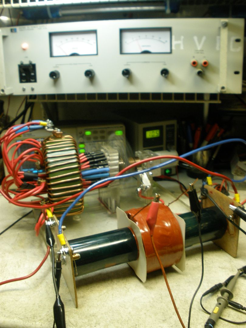 [/IMG]
[IMG] [/IMG]
I am still not happy with signal...but, it maybe brush bad contacts as NOT contacting two elements...but it is going negative....either that or too much noise from PSU...have to check.
I tested the system and works fine...I have the linear PSU supplying V&A...However, due to low resistance, still will not allow me to reach even 10 volts at like 9 Amps...I thought a linear would do it...but do not.
However, I have noticed that as I increase small motor speed, voltage starts rising up, amps remains same at PSU...As Induction greatly increases...but unfortunately I have an issue with brush...and mechanical contact that at certain speed starts sparking big time...seems it is loosing strong contact (maybe a spring went bad)...besides notice that it is not contacting two elements but barely one...no good...so unfortunately I will have to take it apart and repair-adjust.
I want to take motor close to 3000 to 3600 operating RPM's to be able to evaluate and measure the full operational system...
Sorry about that.
In general Part G is working fine, fields are fluctuating great and strong and at the top speed I was able to drive it, which is not much...system did not sparks...nor gets hot at all. Primaries a bit warm, that's it...meaning perfectly stable.
Done for the day of tests.
Regards
UfopoliticsLast edited by Ufopolitics; 01-06-2017, 09:21 PM.Leave a comment:
-
Time to Keep building and testing...
Hello to All,
I am finished with Part G rewiring with 10 awg and more turns than I had before (like 20)...now I have like 44...
But I wanted to share what I have found maybe to be useful for those using bare wire...and do not want to epoxy your setting.
[IMG]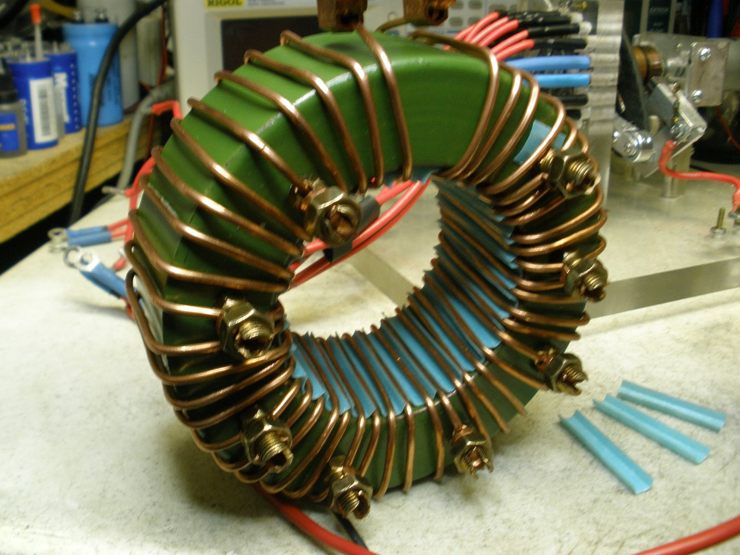 [/IMG]
[IMG]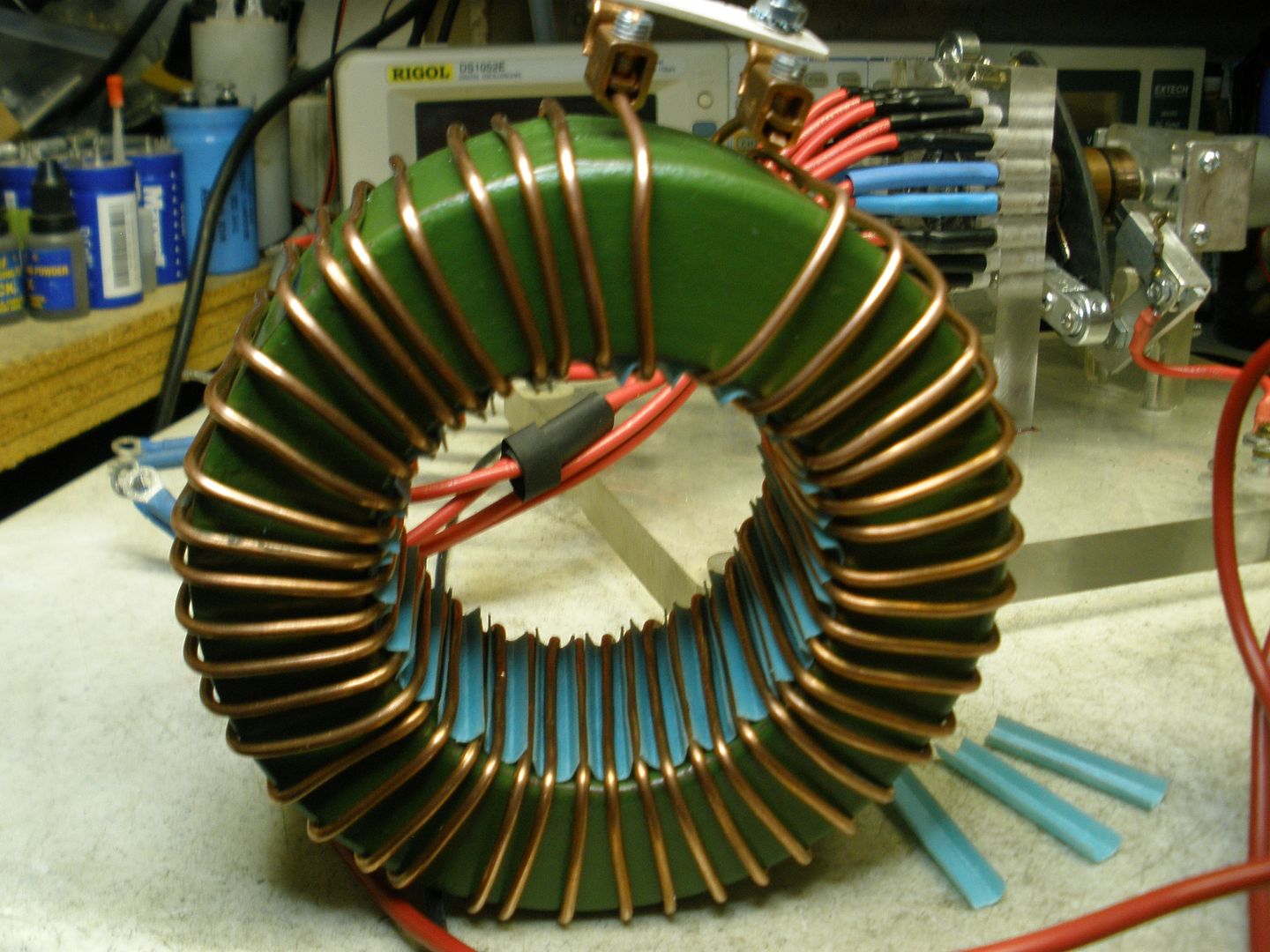 [/IMG]
I used Motor Hedges in the shape of a "U" alternated between each wire loop...and besides isolating wires, it would help to maintain a separation.
I am also testing another configuration of Secondary to see which one will render more Induction...
[IMG]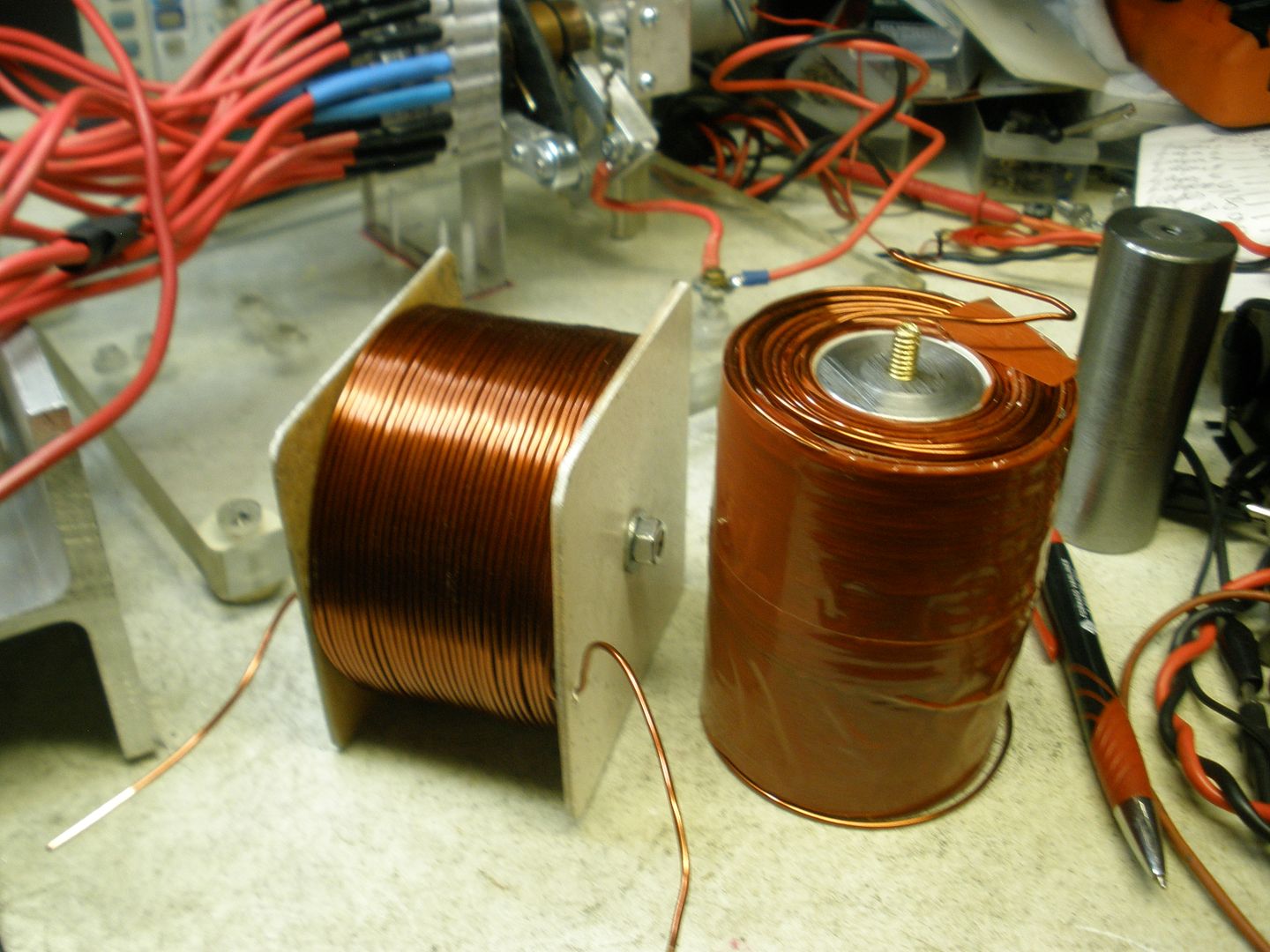 [/IMG]
A shorter Core for Secondary, not only will shorten the Repulsion Magnetic Field sweep area...but, because of getting both Primaries closer...a Much Compact and stronger density repulse field would be generated by the two North Poles.
One thing that I HIGHLY recommend guys...is to build your set in order that you could take it apart easily...use tape, bolts, nuts, taps and die parts...screw, unscrew cores, etc,etc...in order that different types could be exchanged or swapped easily without loosing much time...but, basically not to waste materials...like when you build for a lasting and already tested and working device...We do not have -at least I don't- a huge budget (I only wish..) so we can't afford to waste wire and other materials, including TIME... every time we make one set and it just don't work "as expected"...
Regards and great build!!
UfopoliticsLast edited by Ufopolitics; 01-11-2017, 03:12 PM.Leave a comment:
-
Btw
Just so you people know what is going on with part G , the Primaries and the Secondaries the pic below always helps. the peaks are that side primaries high.

MMLast edited by marathonman; 01-06-2017, 11:05 PM.Leave a comment:
-
Part G
Last night i slept the best i have in a month, even drooled on the pillow.
I think everyone is having trouble with part G because of the Inadequate amount of Induction from their small cores. Figuera used an Iron cylinder insulated and embedded with thick wire that he calls commutator bars. thus i don't see any reason we are on the wrong foot with the commutator as his signal would of been about the same as ours with the commutator VS. the direct brush contact. it will still be stair stepped no matter how you do it but the secondary does not see this as it will be smoother
the three reasons he used thick wire was for One, the least amount of losses associated with resistance as ANY inductor has losses associalted with resistance so what is the best way to reduce it??? thick wire reduces resistance. two, it had a better interaction with the core (Inductance), and three, it was the power supply after initial starting so it had to be hefty as all lower parts of the branch add up to the final supply plus headroom just like ANY power supply would have to.
the pic below is of an Iron Cylinder, notice how much more surface area you have compared to the toroid below it. yes Figuera used a cylinder of Iron in which his loop diameter of his thick wire were VERY LARGE and having much, much more surface contact as a toroid. of course it was insulated and embedded.


thus we are left with either using a toroid with a larger amount of winding's in which we can increase the depth like i did or you can use a alternator core like Doug did that has much more surface area then one toroid.
both will get you a higher surface area in which to have higher Inductance.
EDIT;
I am not saying a toroid will not work, quite the contrary, it will work just add a lot more winding's.
Bottom line is Self Inductance talks and BS walks.
Last edited by marathonman; 01-14-2017, 04:39 PM.Leave a comment:
-
Drained
I will be taking a short break as i am Physically drained. having trouble sleeping and getting up as all the BS is taking it's toll.
Good move cadman and thank you for your kind words.
see you all at a later date.
I must rest now.
MMLeave a comment:
-
@ UFO, yes contradictory to classic science, but nothing is acheived by doing the same thing over and over, if it doesn't have a different outcome, Hey.
@ Cadman glad to see you back, hope all is well.
The only reason i can think of for Doug to wind his rectangle wire on it's side, is that he was allowing plenty of sacrifice of the thickness to get a flat brush surface.
Please if anyone out there knows anything different, please chime in.\
The main direction i will head in with this device is low voltage high amperage DC output from secondaries, as a battery replacement for electric vehicles.
All the best Cornboy.
Leave a comment:
-
Cornboy,
Doug used a slightly different size
Re-Inventing The Wheel-Part1-Clemente_Figuera-THE INFINITE ENERGY MACHINE
His bars were wound on edge, and I bet he applied epoxy filler between each bar...... but in any case when I tried the thin lineaments they were too sparky from particulates that came off the brush I used from the starter motors.The particles eventually made the brush ride on the dust and that caused scorching of the copper strap. the bars can handle more downward pressure. They are not really bars they are 3mm by 5 mm thick after sanding down true and flat Im sure it is less then 5 mm.
BTW, you don't need to use a large lathe, a good machine shop with a surface grinder would be better.
Regards
CadmanLeave a comment:
-
Hey Cornboy, friend Happy New Year!!...I believe you will get to 2017 faster than we will...so be it!!Originally posted by Cornboy 555 View Post
And if You could do that toroid fully wound with rectangle wire, plus machine copper to be smooth..plus sweep brush around each contact...for sure that is the way to go!!...Your Signal on Scope would be as smooth as 100% silk!!...No Bumps no steps at all.
Tapping each wire could have a lot of work...but it would worthy it...plus applicable to many setups...
Yes, even being contradictory to "Classic Science"...a lower resistance primaries would generate a very strong magnetic field...and very cheap to reproduce into multiple primaries sets...Not the same results in spending energy to generate those fields if we have High Resistance as the total sum of all primaries together in the circuit...whether in series (like it is supposed to be) or in parallel.
Happy New Year Cornboy!!
And Happy New Year to ALL!!
UfopoliticsLeave a comment:
-
Hello all,
@ UFO, after seeing, with my own eyes and experimenting, what Part G does, a few days ago i made the decision to scrap what i have built and start over.
I had come to the conclusion, that how Doug built his Part G, was definitely the way to go, then i see your post on the other thread saying the same thing.
What's the old saying, " Brilliant minds think alike, and Fools never differ."
I have located some 6mm x 2mm flat wire, and will rewind my toroid fully with it, with a tap off every turn for experimenting. Also i will go down the path that Mm outlined, and wind my primaries with the same wire, for virtually no resistance and max field strength.
Have found a glass like epoxy that will handle 90 degrees C, hoping that G doesn't exceed that temp.
The large laminated welder core i was given will make 2 large sets of primaries and secondaries.
approx : 40mm x 90mm by 120mm long, for primaries, and the same for secondaries except a little shorter.
I will get started on this shortly, as i have some work to catch up on before Play Time.
Happy new year, and best regards everyone, Cornboy.
Leave a comment:
-
Inductance
I would have to say taking an LCR meter and checking some coils, some with wide rectangle wire and some with regular wire would probably give the same reading with the same winding count. but then you have to realize that NO currant is actually running through the coil so this in my opinion would give a person a false sensor reading.
as L meters do not put ANY reasonable amount of currant through a coil and it can in NO WAY give a proper reading that coincides with actual currant flowing through a wire and magnetic field circulating around a conductor.
the only way to check to see a reasonably accurate test would either test the magnetic field around the wire with currant flowing through it or observe the currant drop as currant is introduces to the wire in which i have done. the results i got were that rectangle wire actually does have higher inductance than regular wire at the same currant value.
this test can be conducted by EVER ONE that doesn't think wide wire inductance is stronger then regular wire. confirm it your selves.
but i have to say at this moment in time, I could really care less what you people do with your device or with what wire you chose. those massively Ignorant sick people on the other thread are draining me. I will take a break to recharge.
MMLast edited by marathonman; 01-02-2017, 01:53 PM.Leave a comment:
-
Not You
I know you know i was not referring to you at any shape or form. the other people.Originally posted by Cornboy 555 View Post
as for the toroid, you have the one you need for the complete system, it just needs more windings.
yes Mr Doug used just one alt core and if i remember rightly it was at 100 amp or above core so that would put it above 1200 watts.
i really cant believe people act the way they do......God help us in our hour of human need .
as a navy seal friend of mine used to say, nothing a 50 cal long range can't take care of. and i said, well put spec.
MMLast edited by marathonman; 12-29-2016, 03:07 AM.Leave a comment:
-
Originally posted by Ufopolitics View Post
Wow UFO, nice looking power supplies, there is just no substitute for good old fashioned heavy duty design.
Hope all goes well with them.
Regards Cornboy.
Leave a comment:


Leave a comment: