Power Supply
UFOP;
quote; 2- Part G Inductance (Lg) should be -at least- EQUAL to JUST ONE of Our Primaries N and S Inductance (Lg=Ln=Ls).
I completely agree. as both inductances are separate from the their magnetic fields, they should be calculated as separate halves of the system even thought the whole coil inductane can be calculated as one unit from low to high or vise verse in part G.
i just wish i could find a formula for inductance that includes wire width as my initial tests show wider wire have a more profound influence of self induction within part G's core.
Quote;
"These old linear PSU's units are very rough built though...just like a German Tank built...will last for ever."
I totally agree, most people i converse with that have these old power supplies say they are damn near indestructable.
Quote;
"@ Mm you said you had a custom 100v 10a power supply, did you make it?."
Yes/No, i am still gathering supplies and parts. have located used toroid for the job that will work just fine though. i plan on making it adjustable from 25, 50 75 and a 100 volts.
the good thing is that once the robust power supplies are made they can be used for so much other things you and i have going on.
MM
-
My New-Old Linear PSU...
Hello Cornboy,Originally posted by Cornboy 555 View Post
I have been "hunting" on EBAY for one of these units for a while...til I found them...Two actually, just to put one together...
[IMG] [/IMG]
The above one is pretty banged up...got it for 20.00 USD...and then shipping was $68.00...cause they weight like 60 lbs.
Then I got the second one much better looking (in appearance though):
[IMG]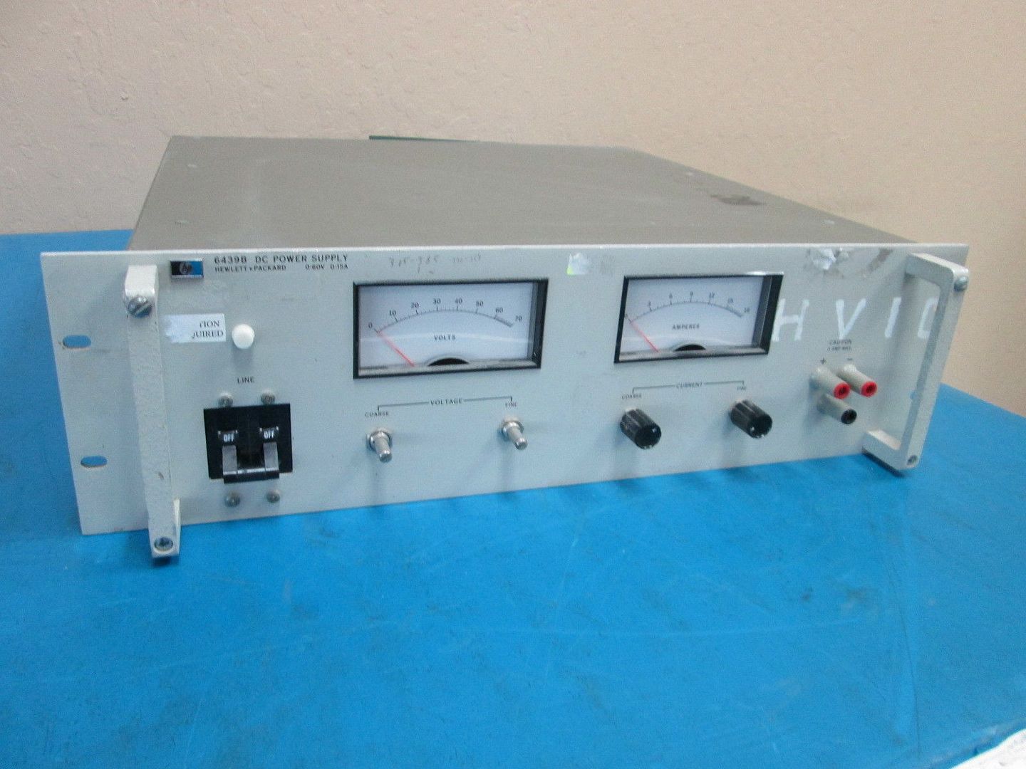 [/IMG]
Both are HP Agilent (now obsolete) 6439B and output is 60V and 15 Amps (900W)...and that is more than enough power.
They both are still in transit...Holidays delays.
Once it is refurbished it will cost around 600-700 USD:
REFURBISHED 6274B EBAY
And the one above is an older model... series 62.
And a brand new decent Brand name of these Linear PSU units goes for around 800.00 USD...for example the one shown below is 60V and 8 Amps and costs 825.00 (without any "optional" stuff, meaning no Voltmeter, No Ampmeter, no Overload protection...etc,etc...and so by the time you get all these things it will climb close to 900.00 USD):
ACOPIAN PSU 60PT8
I believe He did make it...Custom made.Originally posted by Cornboy 555 View Post
This is the "cost" of experimenting friend...actually once we find the correct required power...we don't need it anymore (except for more experimenting...)...just a small battery pack carrying the exact power would do the job as a "start up" fixed Power Source to Generator...once Gen is running it disconnects and could restore power back through a small -built in- charger unit...done deal.
These old linear PSU's units are very rough built though...just like a German Tank built...will last for ever.
Regards
UfopoliticsLast edited by Ufopolitics; 12-25-2016, 03:21 PM.Leave a comment:
-
@ UFO Yep, understand, where did you get your linear power supply from?
@ Mm you said you had a custom 100v 10a power supply, did you make it?.
Regards Cornboy.
Leave a comment:
-
Yes...BUT, the way our job must be done FIRST is by using a LINEAR PSU, (switching PSU definitively will NOT work, take or leave my advice, up to you), In order to find the Right V & A Supply which generates the right Field to generate the suitable Induction on Secondary(ies)...And so, from here, once we have the V &A...Then we could replace it by the exact suitable Battery which would disburse that right kind of Power Output...Originally posted by Cornboy 555 View Post
Understand?
We need to test Secondary Layers V & A (like I wrote on prior) in order to see what is our Wattage Output per Layer, now, remember that as we add Multilayers...Radius or Depth would be increasing...and so, I believe it is better to make -at least- a read out at first and last layers of secondary...depending on Our Secondaries Coil Size, related to number of layers, we may want to add a Mid Layer Reading.Originally posted by Cornboy 555 View Post
And so, I believe We will need to do all these testings before moving on to other sets of Primary-Secondary-Primary...not to really waste our time.
Regards
UfopoliticsLast edited by Ufopolitics; 12-24-2016, 10:13 PM.Leave a comment:
-
Thanks UFO, the other thing to consider is that if we have a secondary to feed DC to part G, we only need a flick of battery power till the secondary cuts over.
So i guess we need more to work out the secondary V & A to supply losses.
Regards Cornboy.
Leave a comment:
-
Cornboy,Originally posted by Cornboy 555 View Post
DEFINITIVELY NOT!!!
You, for sure will burn something there...unless you want to have Pop Corn well done...
Everything is out there Friend...the problem is that you would find a lot of Calculators based on either Air Core, or iron dust, Ferrite, etc,etc...which does NOT Apply to our set up here.Originally posted by Cornboy 555 View Post
So, must check they have Iron or Steel (different ones) Permeabilities Coefficients included in the Basic Formula:
L=�N^2A/l (where number of turns (N) is squared), u=Material Permeability, A=Cross Sectional Area, l=Length of Coil-Core.
The site below have a Calculator for Multi-layer, Multi-row Coils:
COIL CALCULATOR
Another One:
COIL CALCULATOR 2
Another one
COIL CALCULATOR 3
AND SO...TOROID CALCULATOR:
TOROID INDUCTANCE CALCULATOR
No need for it...We got it...Originally posted by Cornboy 555 View Post
Merry Christmas to you too friend!!Originally posted by Cornboy 555 View Post
Best and Warm Regards too!!
UfopoliticsLast edited by Ufopolitics; 12-24-2016, 09:10 PM.Leave a comment:
-
Soo, i take it UFO, that you are not recommending to test my device, hooked up to my 24V 3000AH solar battery Bank.
How do you calculate inductance of certain masses with certain windings???.
OH oHH, i can hear Bistander chafing at the bit, to answer that, maybe on the other thread hey.
Merry Christmas everyone,
Best and warmest regards, Cornboy.
Leave a comment:
-
Battery Testing...Today.
Hello everyone,
I am actually running some tests with Batteries as the Power Supply...Batteries are 12V 33 A/H AGM, Deep-cycle.
[IMG]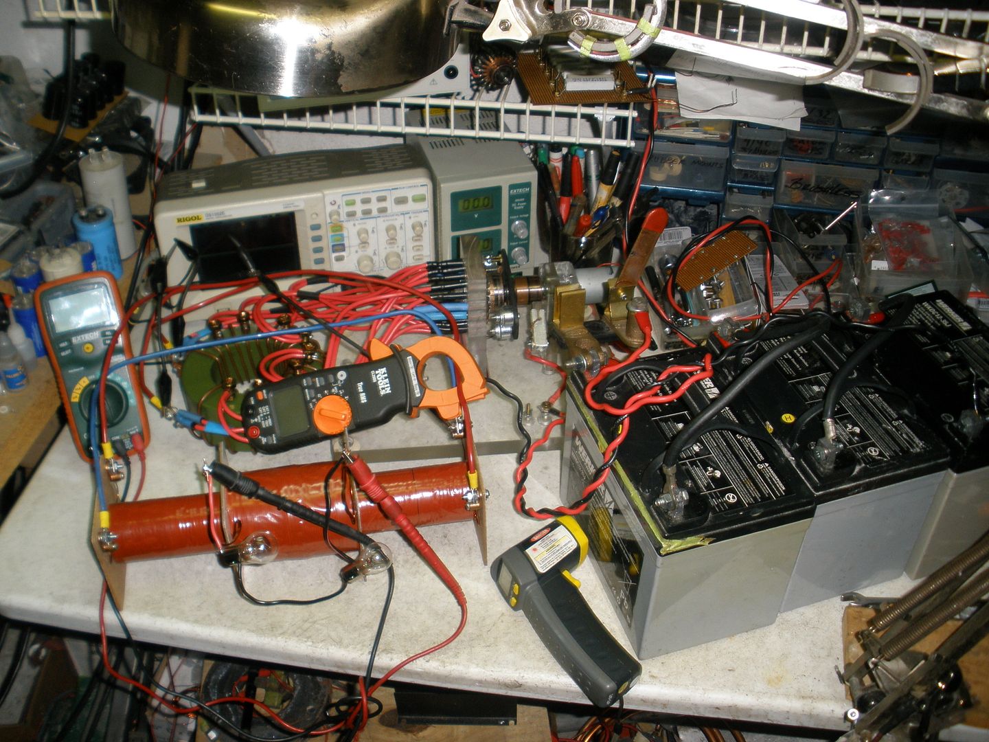 [/IMG]
And here I am just verifying what I wrote previously to Cornboy...
Batteries, once connected to this System...will disburse ALL their FULL Power into it...without absolutely No Regulation on Volts or Amps...but only based on the Inductance Regulation from our Part G...Since We are Operating at such Low Levels of Resistance.
My Part G is still wound with 8 awg, and 20 turns...same way as I had before.
I started with 3 Batteries fully charged to 39.0 V...and they Disbursed 54 Amps...I have a Blade Switch on...and Primaries climbed to 272� F...had to cut off power in less than one minute of running time...Not Good Results.
My next test was with 24 Volts (Two Batteries)...it disbursed -roughly- 30Amps...not good either.
Reduced it just one Battery...and it spent 19 Amps...not good results.
And when I write "not good results" I meant relating to very poor induction at Secondaries...and not just relating to heat and higher amperage.
And the problem bolts down to the way the Dual Signals become (I rather should write "Deform" here) at any of these levels of power...
[IMG]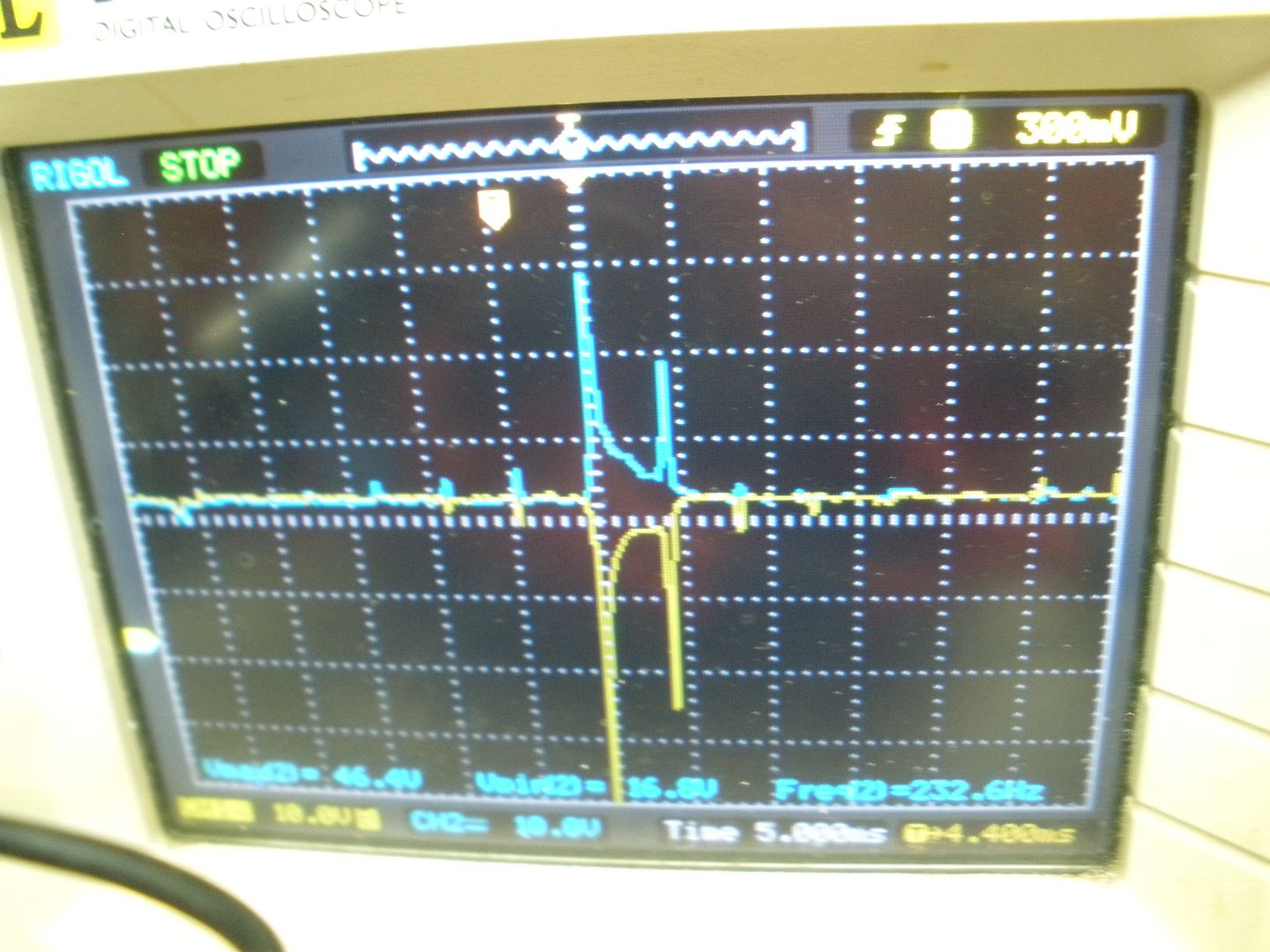 [/IMG]
Above is the Signal for 24V (Two Batteries)
[IMG]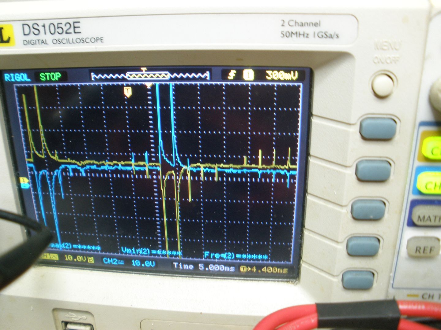 [/IMG]
And above is the Signal for 12V
Note the Rise and Drop off are simultaneously taking place around zero Time.
Collapsing Field Alternatively below Zero Values...NOT GOOD!!
Big difference when I did the Test with 36V 2+ Amp Max out with Lipo Batteries...except they started to burst and dripping liquid...overheated...But Induction was great as Signal was right.
However, even being not such good tests...I enter into a new reasoning (which I will be testing as well) about this whole system.
I will share them below for any comments or suggestions...
Part G Regulates Currents based on Inductance -at the same, exact time toward - Primary(es) N and Primary(es) S Coils.
I would say that INDUCTANCE Calculation from our Part G Coil, MUST BE in completely DIRECT FUNCTION RELATION to our Primaries N and (or) S Coils INDUCTANCE .
I think based on the above we could Establish this Inductance Relations in either Two Ways...
1- Part G Inductance (Lg) should be -at least- the SUM of Our N and S Primaries Inductance (Lg=Ln+Ls)
2- Part G Inductance (Lg) should be -at least- EQUAL to JUST ONE of Our Primaries N and S Inductance (Lg=Ln=Ls)
And just because Part G Inductance Disburses Currents within exactly the SAME TIME to BOTH N and S Coils...I will rather choose number 2 above.
Which resumes that Part G should be NO MORE and NO LESS than the Inductance from one of our Primary Coils Calculation.
This way our System would be able to be tested with different current inputs...
If We choose number 1 option: (Lg=Ls+Ln), then Part G would be operating based on DOUBLE THE INDUCTANCE VALUE to Both Primaries SINGLE INDUCTANCE VALUE within SAME TIME....And I do not see this mode of operation right at all.
I believe if we get here...we will be able to come up with the right Calculations to be adapted to any of our systems, no matter the differences.
Anyways...this is my take on this system....And any opinions welcome.
Regards
UfopoliticsLast edited by Ufopolitics; 12-24-2016, 06:47 PM.Leave a comment:
-
Merry Christmas to All
Hello Everyone...participating or just watching this Thread...
Please let the Spirit of Christmas bring Us into a Unified Gathering of Manhood...trying with all our efforts to make out of this Planet, a better one...a Planet Free from Oil Dependency...for ever.
Then let it be Peace and Love forever, evolving into a Higher Civilized Race.
Amen
Respectfully and very Seriously
UfopoliticsLeave a comment:
-
I agree!
I don't care who you are!
Have a merry Christmas!
Thank you all.
ShadowLeave a comment:
-
Wire
QUOTE;
"On Acetone have to be careful and make first some test to your wires enamel...then see if it removes it...if it does no good to do it.'
yes, good point to bring up as all wire is not equal.
Shadow;
QUOTE; "build a rotary device like yours, UFO's or Doug1's."
No one on this forum is building like Doug as he used an alternator and tarzan fan assembly to house the brush that makes direct contact with the thick wire wrapped around the core. he used a precision grinder to grind the wire at operating speeds from the top to achieve extreme rotating tolerances. we are using the very same concepts and functions though, thus we will achieve the same results. i don't have a precision grinder so alternative methods needed to be devised.
MMLast edited by marathonman; 12-23-2016, 12:16 PM.Leave a comment:
-
Thanks MM,
I have High Temp Clear and Orange Epoxy for those purposes...but I don't wanna do that as of now. Since the bolts and fiberglass plates press against core and wires...so I am just fine for testing purposes.
On Acetone have to be careful and make first some test to your wires enamel...then see if it removes it...if it does no good to do it.
Some enamels do come off...some don't...I recommend to check first.
PSU don't feed primaries right...6V 10A is not enough to build required field....so I will test with some batteries I have charged ...let's see.
Good nite all.
UfopoliticsLeave a comment:
-
Protection
For the people using this style of core attaching with a brass bolt please be sure to have some type of very thin insulation between core (micro barrier) or else Hysteresis and eddies will cause primaries efficiency to drop and heat up and this we don't want.
UFOP a small bit of glue or resin will keep the ends from despooling like i see in your primary either when winding or after.
another trick is acetone and either packing peanuts or ping pong balls. stir together it will melt very nice then dip the coil or spread with brush. dries clear and hard like armor.
use on finished coils and it will look like the pro's.
a word to all, if using transformer laminations you should be able calculate the output from the secondary with the material spec sheet if you have one or even something similar to it. ie watts per lb or watts per inch. that is why you should start with the secondary output you need then match your primaries accordingly.
the reason i can not calculate this is solid pure iron does not come with spec's like laminated silicon iron does that is why i had suggested it.
but from some of the suggestions from UFOP or myself, we will get there. even soldering a test wire at the end of the first layer coil will help determine volts per turn thus not having to cut your coil.
this is the very reason i have not wound the second secondary yet as i need to gauge the output first.
NICE CORES UFOP. and i like your rusty red.
once my coils are good to go all inter connect will be 10 awg, shrink tubing, then taped.
Cornboy; i see your counter balance above the brush holder but not the slot. guess it is covered from the brush plate. balance is definitely the key.
MMLast edited by marathonman; 12-23-2016, 12:20 PM.Leave a comment:


Leave a comment: