Stuff
Wow that motor looks great
Motor looks great!
Two coils finished. I do not recommend my version of winding coils on cores. Use
bobbins instead like MM did.
I got worried about traces of iron or steel in my brass connecting screw for my coils.
I did a test with my biggest magnet and I think brass is fairly pure. The brass screw
just falls off my finger smashing magnet!
Shadow
-
Motor
Found what looks like a very good candidate for motor drive to test part G.
also they carry the controller plus a heck of a lot of other things one might want or need.
pic below is motor, as you can see very good size and robust.
just about the size of my cores after i cut them.....nice !

or this one.
3-PHASE BRUSHLESS MOTOR, USED | All Electronics Corp.

UFOP;
what do you think of these motors ??????
MMLast edited by marathonman; 12-20-2016, 07:59 PM.Leave a comment:
-
Cores
Just finishing up some loose ends before i start the inter connections. looking for a heavy duty motor and commutator to test while i finish up the electronics. still need the Mosfet board and Mosfets thus the commutator and motor for testing are cheaper.

MMLeave a comment:
-
Part G
This is good, i do see the battle scars on them and yes balance between primaries is very essential and mandatory for proper operation.
Confucius say; man who use inductance to control currant stay cool when electrified.
"The Induction at secondary is really awesome friend!...the more small motor spins...the brighter the bulb gets without source being any higher."
and just think, a few months ago you never new what joy you were heading in to.
Figuera gets my vote for physicist of the century, the rest are all clowns.
MMLast edited by marathonman; 12-20-2016, 03:18 AM.Leave a comment:
-
Originally posted by marathonman View Post
MM,
Those brushes have been to hell and back... ...the burning is not from these tests.
And yes, every wire and bolt must be rated for higher amperage...just for safety....and 10 gauge is perfect for wiring all.
I had some gator clips...and they got really hot...which means losses...no good...All wires must be the same gauge attaching all connections.
Even though, there is one thing I forgot to mention...I am only testing one small set of primaries...not the real deal am building, which are heavier in mass and thicker wires...I am sure as you have said, there must be a kind of "Inductance Balance" between Part G and Primaries...so the inductance "network" works fluently back and forth without any differences.
The fact that Part G is that cold...may mean that must Inductance is finding too much reluctance (resistance) at Primaries...which is no good for them, as they will do get hot if there are too much difference.
Inductance Balance is the name of the game here...
The Induction at secondary is really awesome friend!...the more small motor spins...the brighter the bulb gets without source being any higher.
These are just preliminary testing and I need to make many more...with the real primaries and full wiring with right 10 gauge..
Regards
UfopoliticsLast edited by Ufopolitics; 12-19-2016, 11:08 PM.Leave a comment:
-
Low Sparking
It was relayed to me as to your effects of almost zero sparking. also that once the system was running very little brush wear occurred which is rather mind boggling. your twin brushes still need some wear to completely line up faces so this is very good news. i see some slight burning at the brush, i hope further wear will fix it.
very odd action from the amperage especially since part G allows only so much currant through the system. this is something that i did not anticipate and i do apologize for that. seems we need to monitor this through out the build.
very glad to hear your freezer part G works as planned.i never had a doubt in my mind just waited for everyone else to catch up to the technology.
outstanding news great work UFOP.
MMLast edited by marathonman; 12-19-2016, 10:10 PM.Leave a comment:
-
Mechanical or Solid State...
Hello Glen,Originally posted by GlenWV View Post
Are you going to make the mechanical rotary switch or electronics first?
As you know I am doing mechanical switching...and so I can only tell you about it so far...'
I am currently test-feeding system with batteries...non regulated... and even batteries disbursing only 2.5 amps on first tests...it blew the copper wire (actually melted it) that comes from the slip ring fixed brush. it was from a car alternator slip ring brush...and they are not good. So I changed the whole thing to a double motor brush with heavier wire...and now it works excellent. Got brush from one of those cooling fans motors, they are rectangular so fit two on the aluminum sliding channel I built out of a square tubing.
Below are couple of pics to my new slip ring dual brush assy...
[IMG]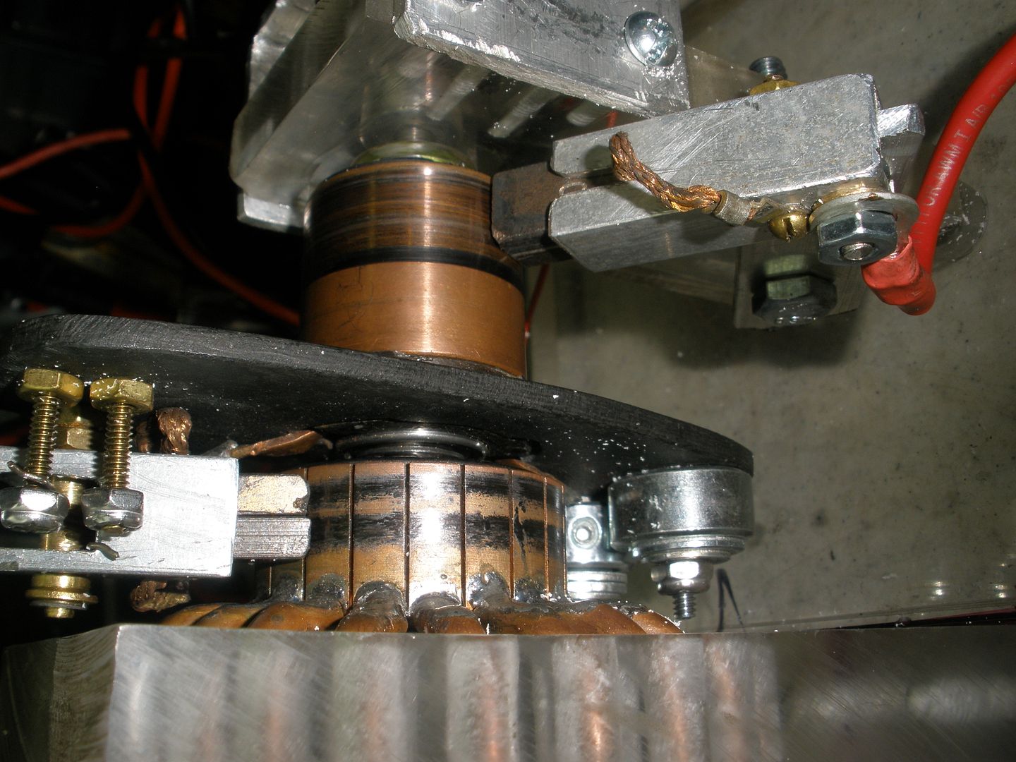 [/IMG]
[IMG]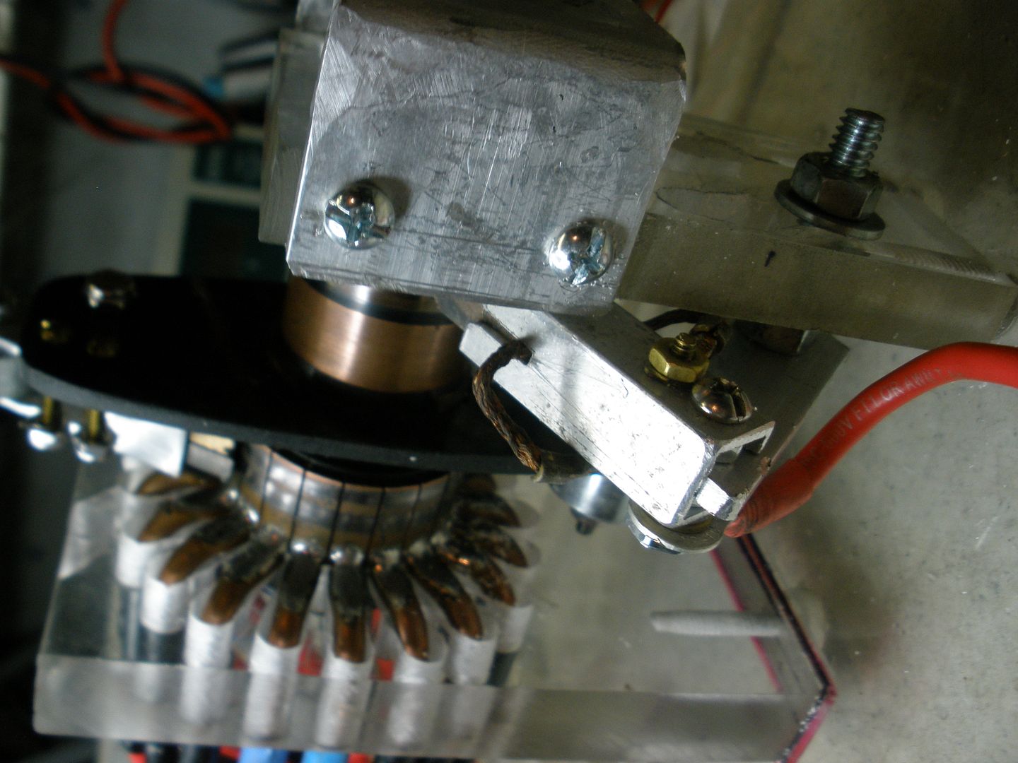 [/IMG]
What I see on this system, is that because of the so low resistance, it amplifies the effect of currents even being as low as 2.0 amps making them act like 10 amps.
My recommendation is to go above the running amps spec's as related to all connectors and fasteners involved. Plus everything must be very tightly attached.
And so, once everything is set tight and firm...plus the right gauges correct...system will not even spark at any of the brushes...do not ask me why this happens....because I really can not explain it either.
I would be calculating the MM recommended spec's...which are 50 Volts and 4 to 5 Amps...but like I said...these 4 amps will act like 10 or 15 amps due to low resistance.
In the first running minutes electromagnets will get warm...but as system stabilizes it will start cooling off...not Toroid Part G though...This Part would be a freezer...
Regards
UfopoliticsLast edited by Ufopolitics; 12-19-2016, 09:57 PM.Leave a comment:
-
Ampacity
Greetings all:
My commutators have arrived, but I think that they are going to be a bit on the fragile side for this application.
I found this: https://www.toledocommutator.com/
They seem to have everything.....(dear Santa...)
My question is: How to size the things? How many amps do we need for the commutator brushes, and collector rings to handle?
The #8 bare copper is good for at least 40 amps, and the #6 should be good for 50.
I think MM's FETs are rated pretty high. (Reminds me, my UTSource order hasn't arrived yet. Gotta go look in on that.)
So, are we going to hit it with that much??
Another thing, would a higher number of commutator bars be helpful? Like 36 would make one tenth of 360 degrees. Or, would that just complicate tuning?
Perhaps I am over thinking this thing.
Merry Christmas to all,
GlenLeave a comment:
-
Two sets
I have two complete sets done so i will begin inter connections. i have 10 awg red wire used for part G taps left over so i will use that for all inter connections.
i will post pic of semi finished sets before i attach 10 awg and outer tape wrap plus working on mounting base.
MMLeave a comment:
-
Cores
Turned out really good shadow. using two sets to tune would be good idea to work out any bugs or anomalies then add the rest.
UFOP is right we are all slowed down during the holidays due to family obligations.


yesterday i helped my black mechanic friend tear a car rear end and tank a part. the tank is set in a cage like frame that has the rear wheels and suspension built in. well, the info he had said it would take 4 hours but we nailed it in under 3. we laughed, joked and had the best of time and not once worried we were doing the wrong thing. it reminded me of the Figuera device as most people are afraid to let go of their outdated ways, thinking and just do it. jump in with both feet and an open mind thus you will be surprised at what you can learn and accomplish if you set your mind to it.
Merry Christmas to all the wonderful followers, readers and especially to my fellow builders who are helping me spread this wonderful device around the world. thank you all and God bless you and your families.

and especially to the people that have donated to the Figuers cause and helped me get to the point i am presently at. we still have a ways to go so please feel free to contribute to this wonderful cause.
Have a Very Merry Christmas and i hope your new year is blessed with Figuera.
MMLast edited by marathonman; 12-18-2016, 09:35 PM.Leave a comment:
-
One unit
Below is one unit brass screwed together. Total weight
is 14.5 lbs.
http://www.energeticforum.com/attach...1&d=1482005291Leave a comment:
-
Commutator
Shadow;
I see your dental work and why you did it. worked out well as an after thought.
Cornboy;
I am not worried about size, it's the thickness that is most important. I am sure it will be ok, looks thick enough to handle some amps. and some people were wondering why i chose such stout Mosfets......em now you know why as there was a method to the madness. but remember the peak currant is only for a short time constantly rising and falling.
also why my Mosfet board is 2 oz copper.
you must realize the winding of part G is important as it dictates all currant flowing through it. you can wind it to give you 2 amp peak or 10 amp peak, it is entirely up to the builder and how may winds are on the toroid when brush is at peak.
there was a conversation on the other thread as to which was more important, currant or voltage aka emf.

it's a round about viewpoint but you get my drift, cause and effect.
MMLast edited by marathonman; 12-16-2016, 10:20 PM.Leave a comment:
-
@ Mm, the 16 bar commutator is quite small in comparison to 1500va toroid, only time will tell if it can handle the currents involved here.
If we were switching a motor with reversing currents of the VA we are using with CF device, i imagine it would fry in a very short time, it is from a small electric motor.
However once the device is started, i am hoping for the recycling of currents, from the primaries, to G, will draw very little amps, and the comm will be fine..
This comm is very affordable,and great for a starting point.
Regards Cornboy.
Leave a comment:
-
Dental work!
Well, I had to do a little dental work on my design?
I got lucky, I didn't even touch the coating on the
wires. If you consider this bragging then you would
be correct.
Shadow
Click on picture to view bigger one!
Famous saying from a famous test pilot = Tony LeVier
"I WOULD RATHER BE LUCKY THAN GOOD!"
http://www.energeticforum.com/attach...15_resized-jpgLast edited by Shadow119g; 12-16-2016, 08:26 PM.Leave a comment:


Leave a comment: