Change with pictures
Plastic?
The rings are Acrylic 025" they are a tight press fit on the 2" iron round bar.
The iron bar sticks out on each end a very little 0.013" so that they will meat
each other. The winding's are 3.214" wide.
The middle core has two #10 by 32 brass screws, heads cut off for joining the three cores to each other. I never thought of gluing the ends together...brilliant idea I think I can still do this...will make a mess, but as I'm a mess...who gives a crap!
Thanks for all the support!
Shadow
http://www.energeticforum.com/attach...1&d=1481913725
http://www.energeticforum.com/attach...1&d=1481913777
http://www.energeticforum.com/attach...1&d=1481913755
-
Good
Shadow;
actually sound fairly good as viewing the pics it looked like a half inch wide. connections will be fine as long as the brass has no ferrous material in it but resin is good to. if a magnet is attracted to the brass screws it is not good and will heat up from the secondary AC action . maybe even adding resin along with the brass bolt then buff out.
i resined them together then semi buffed/cleaned them up below. when i install on mount i will secure then ends as to not move at all. the resin is holding fairly good as i cleaned the connected parts with Acetone before resin process. the end of the core is recessed in slightly from the bobbin so i can mount and align ends to a protruding round mount. just enough to hold it in position fitting nicely into the bobbin at around 1/16 of an inch depth.

UFOP;
Looks great, not something your average person can build but great none the less, can wait to see it in action as i know you are very excited to see it rotating pounding out some va.
i am looking for a small motor as we speak so i can finish my testing and tweeking before my electronics are done so all i have to do is connect the electronics and fire it up.
All;
just reminding everyone, my electronics is to mimic brush rotation ONLY and has NO other function. this allows part G to do all it's functions it so wonderfully does.
MMLast edited by marathonman; 12-16-2016, 05:29 PM.Leave a comment:
-
About my Rotary Switch...
Hello to All,
This post is basically dedicated to those who are going to be building a mechanical switch on their Figuera Generator...
So, this is the way I built my Rotary Switch...and below is a simple sketch showing the main and basic structure:
[IMG]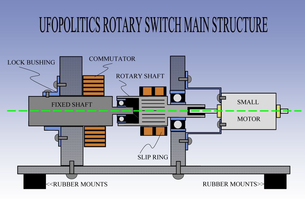 [/IMG]
First I would say to scrap around for an Automotive Alternator...preferably a German one, mine is from a VW ...cause it is better built, plus the Slip Ring and Splined shaft will come out easier without cracking slip ring mica..Now, this splined shaft will become my rotary shaft, which hooks to motor on one end...and to bearing which mounts on the Fixed commutator shaft.
So, I highly recommend to start from here...bore the Rotary shaft in order to fit a bearing within...which Inner Diameter will fit into the commutator fixed shaft, reduced end.
Commutator Fixed Shaft was built from a regular 1/2 inch iron rod, then lathed and reduced. (I actually had to build two of these fixed shafts, since my previous commutator was too small.)
These Two Shafts MUST BE Perfectly center aligned (can NOT Wobble not even a bit!!...or mechanical drag will kill you!!!)...and just with the "floating" bearing between both shafts, the assembly should freely spin while holding any one of the two shafts.
This is your Rotary Switch Main Structure...the center where every thing else will be built around...and so, it MUST BE perfect!!
Unfortunately all this work must be done in a Lathe, plus you should have the proper tooling to drill or bore perfectly centered holes in rods, ...no hand drilling will work here guys, do not waste your time and money...if you do not have a Lathe...then have a Good, meaning, accurate with small projects...machine shop build this simple two shaft assembly for you.
The DC Motor I got it from one of those Battery Operated small Fans...Mine is a 12V from 8 C Type Batteries 1.5V ea which seat on Fan base...this motors use only milliamps and have a lot of torque....they should also come with an AC Power Supply.
RC Brushed Motors will not do this job as they are wound with thick wire and few turns, designed for speed and no torque...they will drain high amps when under mechanical load and so get very hot!!.
I honestly do not know if the 3 Phase RC Brushless DC Motors would be efficient and do the job...since they require a special ESC (Controller) and it will become an expensive deal.
As I do know the 2 phase Brushless (from PC small fan types) will definitively NOT work!!...as they lack the required torque.
At the end of Commutator fixed shaft I installed a Bushing welded to a Washer (in blue, the "Lock Bushing")...which serves as a mechanical lock to fixed shaft and commutator...plus to align whole set.
Resuming here...the "heart" of this whole device bolts down to the Splined Alternator Shaft plus work done to it...It will need must of the Lathe work...as the Motor end also needs to be bored to fit your Motor Shaft...easier you could just add a threaded bolt to lock shaft in place...I went more fancy on this end, as I wanted to test different size motors...so I built an adjustable Dremel Chuck Assembly on this end.
Check for both shaft "play" between them, once assembled, and make sure rotary one would not rub with any fixed component causing any drag...I had to add like two "E" Clips and washers to prevent this from taking place. Realize that must Motors must operate within a small shaft play range...and must NOT be forced to just one static position of its shaft or else will consume more power.
No brushes are shown here for easier understanding of basic structure...and the space between rotary shaft (where slip ring ends) and fixed shaft bigger diameter start... is where I mounted the rotating Brush Assembly plus Counterbalances.
Regards
UfopoliticsLast edited by Ufopolitics; 12-16-2016, 04:29 PM.Leave a comment:
-
Plastic?
The rings are Acrylic 025" they are a tight press fit on the 2" iron round bar.
The iron bar sticks out on each end a very little 0.013" so that they will meat
each other. The winding's are 3.214" wide.
The middle core has two #10 by 32 brass screws, heads cut off for joining the three cores to each other. I never thought of gluing the ends together...brilliant idea I think I can still do this...will make a mess, but as I'm a mess...who gives a crap!
Thanks for all the support!
ShadowLast edited by Shadow119g; 12-16-2016, 06:39 PM.Leave a comment:
-
Headroom
I was looking at the 16 section vertical com yesterday and noticed it was rather small. i was thinking of getting one to build just to test my part G until i have everything for my electronic brush rotation. is it flimsy or is it ok to use???
QUOTE;
"to have headroom in part G does this refer to the volume of the G core, in relation to the volume of the primary cores?."
To some extent yes.
When i was referring to head room, all power supplies must have headroom ie. the sum of all lower branches plus room to operate at an efficient level.
part G is no exception to this rule so all lower branches in your case will be the primaries at high, the primaries at low, your motor driven commutator and some slight losses all added together plus around 500 va for headroom to be efficient in it's operation.
i do not know what your final driving voltage and currant is but as long as the total wattage does not exceed your va rating of your toroid minus 500 va.
example; suppose you were using 5 amp peak for your primaries and 2.5 for your low at 100 volts plus a 2 amp 24 volt motor to drive your commutator. well the primaries are 7.5 amp x 100 volts is 750 watts plus 48 watts for your motor. the total is 798 watts plus lets say 100 watts for losses. losses will not be that high but it is just example.
so we have 898 watts total plus 500 va for headroom so your total will be right at 1400 va total for your part G core. having a little more will not effect operation of the device. also remember all power for electronic must be factored in if using electronic timing.
i hope this clarifies things a little.
And yes, HAVE A VERY MERRY FIGUERA CHRISTMAS.
MMLast edited by marathonman; 12-16-2016, 10:59 AM.Leave a comment:
-
Hi Mm, and all, made my rotary brush switching, but not happy with the quality or robustness of it, so take two, is under way.
Will be cutting up my transformers shortly for primary cores, so have a question, Mm you said early on, to have headroom in part G does this refer to the volume of the G core, in relation to the volume of the primary cores?.
Happy Christmas and Building everyone,
Regards Cornboy.
Leave a comment:
-
Ends
Is that plastic rings on end of core or layers of tape???
EDIT; SHADOW; When you assemble your cores and have them butted next to each other the combined gap might be on the large side. maybe some thin rings lathed from plastic would fit the bill. just something to consider in your building process as it would not be advisable to have large gaps between your primary and secondary coils.
i wound a primary bobbin in 15 min earlier, three layer to. all i have to do is seal/secure with resin. bobbins sure make it a snap. the good thing is the bobbins can be made square also when i build 3 x 3 x 6 primaries and 3 x 3 x 4 or 5 secondaries when i get transformer material.
MMLast edited by marathonman; 12-16-2016, 10:33 AM.Leave a comment:
-
looks great!
I finally got a picture ready for sending...trouble with my phone connection. As you can see these are my cores. I thought it would be easier to use clear 2" tape covering the core then wind the wire on the core. Well, it takes longer and will not work on my winding device.
Oh well, I will probably continue...just takes longer!
http://www.energeticforum.com/images/attach/jpg.gifLeave a comment:
-
Cores
Yep, i can get a good drill motor from the pawn shop cheap to.
Here is a shot of my iron cores after i resined them together. all i need to do is polish them up and slip on the bobbins. i will begin wiring up everything very shortly.

MMLeave a comment:
-
Winder
Looks like the one I have.
Great idea about the drill motor!
I rigged a winder on my early 1950 metal lathe.Leave a comment:
-
Listening
I wish EVERYONE LISTENED as well as you do. this is a very good quality as do not leave no stone unturned when it comes to the Figuera device.
Skimming over important research that has been posted is not an option thus aiding the understanding of the Figuera device and operation .
.
to many people are skimmimg over research and missing very subtle details that are vital. each and every pic posted should be studied intensely and understood before moving on. this is not happening on the other thread at all.


now i know what you meant by cones.......very nice. mine are cheap plastic and shaft is 3/8.
the black knob above the handle is where i will be attaching a drill motor with a foot peddle. it is the same shaft as the bobbin holder is on.
MMLast edited by marathonman; 12-14-2016, 09:10 PM.Leave a comment:
-
Cones3
Your coils could not look any better!
You work a lot faster than me.
I went ahead and made myself a set of 2.5" cones(Didn't burn down the shop or house!). I am looking for some 3" plus aluminum for 3" cones just in case.
Shadow
http://www.energeticforum.com/attach...1&d=1481742404Leave a comment:
-
I'm good
Nice bar stock.
Thank you shadow but the wood seams to be doing just fine and yes i watched a Corvette with a high performance magnesium block burn to the ground like no tomorrow. he kept yelling for the fire department to put out the fire but if water was introduced as magnesium was burning it will explode. magnesium burns at 3 to 4,000 degrees.
needless to say by-by Corvette.
it worked especially good at getting even with people in high school as a small strip from chemistry class was dropped through the vent of their locker it would burn through every book they had.
i wasn't mean, i just got even.
not working today due to weather so coil winding is in order.

Edit; added later.

MMLast edited by marathonman; 12-14-2016, 09:08 PM.Leave a comment:
-
Wood
I looked back through the pictures and found out you used wood! Good choice as the 2.5 aluminum I had was made out of Magnesium! Over heat and you have an unstoppable fire!!! I will still do it if you want.
ShadowLeave a comment:
-
Cones
How did you get your winder to hold the bobbins? I have a lathe and 2" or 2.5" aluminum bar stock. I would be happy to make you a pair of 2.5 inch to .85" bobbin holders to fit your winder if you would like. Aluminum looks bad but is not!
Can't remember how long I have had these aluminum bars??
Must have the size of the threaded rod on your winder.
Thanks
ShadowLeave a comment:

Leave a comment: