Originally posted by Ufopolitics
-
Mm, are your primary and secondary cores and coils going to be the same length?.
UFO, nice work friend, finding the balance between G and primaries i am sure will be critical.
regards Cornboy.
Leave a comment:
-
Interesting reading
This will get you thinking about both feeds acting in opposing mode and their relationship.

MMLeave a comment:
-
Invite
OFOP;
"Plus We need Netica Toroid Spec's at 12V test to see if it matches with my opinions here... "
very good start then compare....good idea.
ps. i was referring to inductance calculation chart not the other.
MMLast edited by marathonman; 11-22-2016, 08:41 PM.Leave a comment:
-
Agree there MM, it won't do...doubling 8 awg turns to 40 instead of 20...won't add up but maybe milliohms.Originally posted by marathonman View Post
The way I see it...we need a Minimal amount of Operating Ohms on System to be able to achieve positive results within a safe zone.
Absolutely, and I was looking already at your chart...:Originally posted by marathonman View Post
1000 ft of 8 awg wire would give us 0.6282 ohms. (Too Low ohms plus too much copper volume)
1000 ft of 14 awg will be 2.525 ohms (which is too High IMO considering just for Part G)
Now, thinking out loud...:
We need to reach a balance of the Magnetic Fields between Primaries and Part G, based on amps-turns and ohms...knowing -as you have stated before- we need some extra room at Toroid Part G...However, this extra room should be calculated as we do not want half feeds to primaries at Max because of too much head room...nor running short either when retracting primaries are shoved back into Part G.
And so I believe head room would have to be split between both Toroid halves, divided by their Outputs line. In order to separate both functions:
1-Fill to Max
and
2- Suck to Min
where both take place simultaneously...no matter that these actions alternate constantly ...since we have identical primary cores.
To run calculations properly I would be using same gauge wire (14 awg) for Part G as Primaries, just as an example to make it simple. And so, we should base this balancing approach on Amp-Turns plus ending ohms on all components.
Originally posted by marathonman View Post
I know MM, sorry about that, but it was basically dedicated for others who have not started building and are reading here...to realize this facts.
If any Building Member here have an opinion please join in!!
Plus We need Netica Toroid Spec's at 12V test to see if it matches with my opinions here...
Regards
UfopoliticsLast edited by Ufopolitics; 11-22-2016, 04:45 PM.Leave a comment:
-
ohms
I doubt it would even raise the ohms that much if you doubled the winding count.... still will be very low with proper amp turn.
do the calculations and let me know please. or us rather as we are a
team.
and i am well aware of what we are dealing with UFOP and a reminder is not really needed on my part.
MMLeave a comment:
-
Originally posted by marathonman View Post
MM,
It is not about High Ohms, as I do realize that we are playing with Inductance here...but to wind here enough Amp-Turns related to Toroid Iron Core Size/Volume VA Capacity.
If we do not build the suitable strong enough, magnetic field, within Toroid iron core...it would simply won't work.
MM, please remember we are not using pulsing DC to feed our system...but a straight, linear DC Input here...so, the only way we will not heat up this radical short circuit system with so low resistance from a straight 50V/5 Amps (as a minimal feed)...is by sinking/transforming this Energy into a suitable magnetic field within Toroid Core...and the way I see we can do that IMHO...Is by using a higher number of amp-turns.
And I am talking about increasing resistance maybe between 1 and 2 ohms...not much though since we are working with heavier gauge.
I will be using the chart you gave us...to calculate somewhere around these values.
Regards
UfopoliticsLeave a comment:
-
Part G
Now why do you think Figuera used a deep core and thick wire...... more core exposure. since you have the core already try doubling the winding count on part G and use tap at every other wind. all that is happening is not enough inductance due to not enough winding's exposure to core material. do not throw wire away just add to it.
i have posted the formula for inductance.
HIGH OHMS IS NOT THE WAY TO GO TO COMBAT LOW INDUCTANCE MY FRIEND.
Cornboy;
i would suggest laminated transformer core and not powdered iron or rods as you will be wasting your time and money. old or even burnt transformers will work fine. i would be doing this if i could afford it as i found a 75 va three phase for 199 on ebay. enough for an entire build.
the pick i posted will have the secondary bobbin increased by almost 1/2 inch larger and cores are resined back together.
MMLast edited by marathonman; 11-22-2016, 03:03 PM.Leave a comment:
-
About my build...
Hello to All,
This post is basically for those building Part G with heavy gauge wire as low turns...plus if any of you are thinking of powering up Toroid and Primaries (I will refer to as the "Exciter Circuit" as a whole assembly) with a "Regulated Switching Output" PSU.
First off I used my brand new "Switching Regulated" PSU that I have posted previously...a "Circuit Specialist" brand name which "supposedly" delivered 60V driving 10 Amps...in order to power up the Exciter Circuit simultaneously regardless of resistance...plain and simple BS!
Power Source of this kind will never, ever deliver full VA with such low resistance values at Toroid plus Primaries...period!...it will raise amps to max (10 A) but Voltage will remain around 2 Volts...which will never, ever generate the required magnetic field at either one of the three components of the exciter circuit.
We will need a LINEAR (not switched) Old type Transformer and heavy diode bridge from AC wall outlet with suitable potentiometers to regulate V and A separately....with nothing more as a "built in protection circuit" that a mere VA Rated Fuse. Then we must start dialing output very slow and precise while driving our Rotary switching either mechanical or electronic (Solid State).
So, if we still have no other recourse but to keep using this kind of regulated switching PSU...then we will need to increase Resistance by higher number of turns...and maybe a not that heavy wire at all Exciter Components.
Below are some pics of my set up:
From previous post where I uploaded the wound Toroid...I wrote that I am using 20 Turns of 8 awg bare wire, as also a 20 elements commutator at switching, well, same spec's with this test:
[IMG]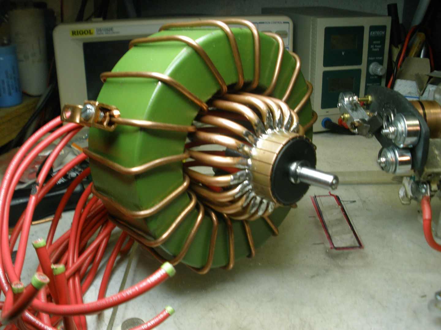 [/IMG]
I used 3/16 copper tubing to attach to each comm element...
[IMG]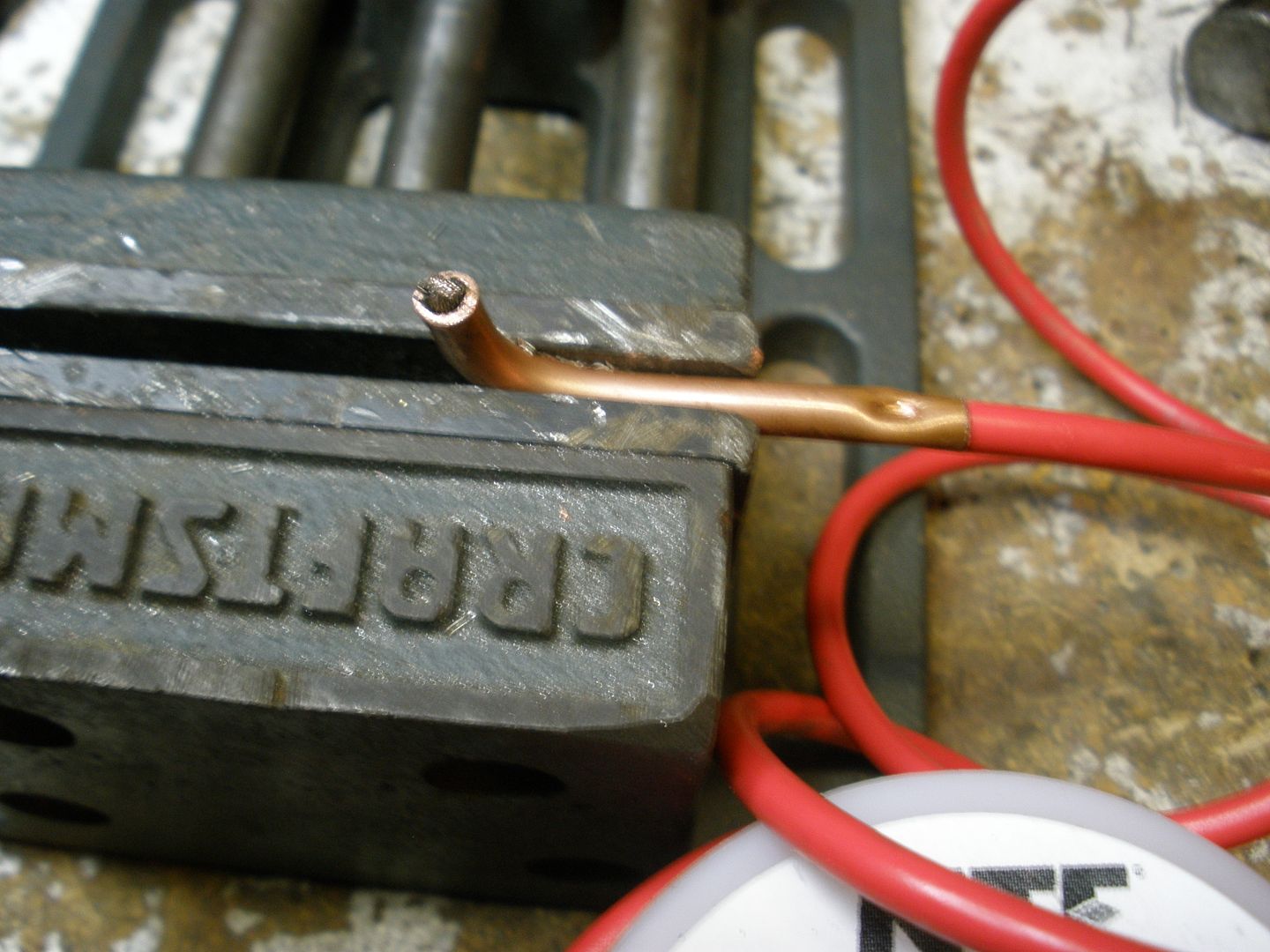 [/IMG]
Above you can notice I ran 10 gauge stranded wire all the way out of the "L" tubing, then press it at end, plus at commutator element ends with a modified by me Heavy duty and huge Pliers which I used before to put together hydraulic lifts steel cables...then melted soldering at both ends of "L" copper tubing with my 175 Watts Gun:
[IMG]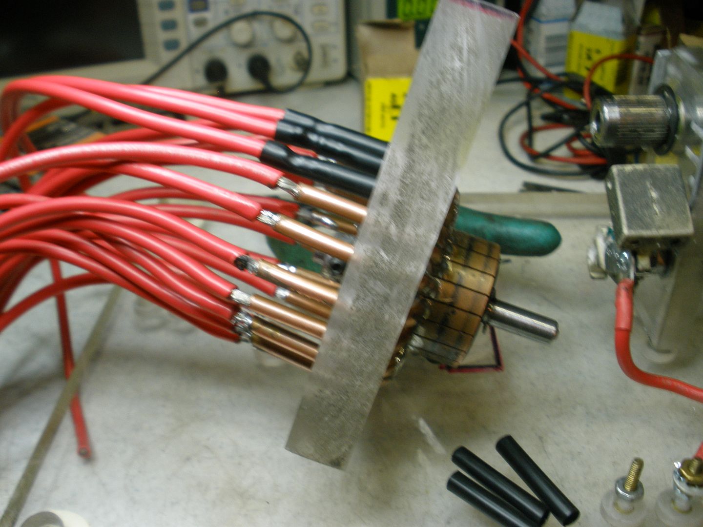 [/IMG]
[IMG]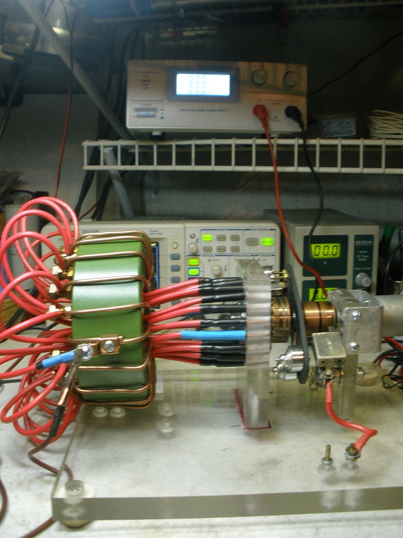 [/IMG]
Above pic is the whole set up wired up...
And yeah...it looks great...but it don't work with my PSU...
The way I see this whole Circuit...there are some main aspects We all must have in mind in order for this System to work as we all expect it to...
1- First than all, at Toroid Part G Core we must Generate/Develop the suitable Magnetic Field in order for it to regulate Currents at both outputs (Hi-Lo) based on pure Inductance and Reluctance.
And so...in order to build this suitable magnetic field within a T-Iron Core of around 1800 plus VA rating...we need to calculate the suitable Amps-Turns per square area based on our VA Input.
And here, IMHO we need to apply the Ohm Law for Magnetic Circuits...or else we all would be winding toroids for a while here...with all kind of different wire awg and number of turns spec's...
As I would like to ask Netica about his set up and spec's* of the Toroid wound he used...and I know he was testing just 12V...still it would be a good start to use some calculations from there.
@Netica the Spec's* am referring specifically to are: Toroid core VA rating or thickness and ID + OD, as number of turns and type of awg wire that you used in the shown test which gave you that Scope signal. (linked to post)
@Cadman: How is your build coming out my friend?...Any results yet?
As we construct here...we must post our failures as our positive results, with all the specifics for either results...as I believe it would serve others not to spend their time with a set up which would not work properly. It is the only way I can see that we all would advance here.
Regards to All
UfopoliticsLast edited by Ufopolitics; 11-22-2016, 02:08 PM.Leave a comment:
-
Yeah, just can't find pure iron rod in Aus, for love or money.
Will probably use either sprayed copper coated mild steel welding rods 1.6mm dia, or iron powder with epoxy, for cores.
I have left over 30mm id bobbins 75mm long for primaries, and will halve the length for secondaries, probably a string of 5 electromagnets, one for power to run device.
regards Cornboy.
Leave a comment:
-
Cores
Quote;
"the pic i have is the pure iron cores cut to stop eddy currants from secondary to primary before rewinding with 14 awg wire."
That my fellow builder is self explanatory but the purity is 98.8 if i am correct and the diameter is 2 inches.
please do not feel compelled to buy this stuff as pure iron is absolutely disgusting in price and you would be better off buying a three phase transformer and stripping it for less. it will accomplish the same thing.
still drooling over that garlic.
Shadow;
8 awg ground wire will get you there safely my friend with less headache.
MMLeave a comment:
-
Hi Mm, are the cores you are using mild steel or pure soft iron, and what diameter?.Originally posted by marathonman View Post
Nearly finished harvest, will start build shortly.
Best Regards Cornboy.
Leave a comment:
-
Ha...bad luck!
Oops!
You are right..........I got caught up in the picture of the copper strips you posted on the eight and ninth.
Oh well, I can get Number 8 locally a lot quicker.Leave a comment:
-
Ouch !
EIS did not have 14 awg on hand. like most corporate America, they are cutting supply thus direct signs times are getting bad. wire will be here in a few days. my primaries will be rewound then pics will be posted. remember to always follow winding guidelines i have posted.
we need to get these devices built before crap hits the fan. as i understand it the Rothschilds and the Rockefellers are planning to crash the market now that Trump is in office. i just hope we are finished with this device by then.
i have pure iron core that i will be using as that is what i have on hand. i can't afford anything else and haven't the funds for laminated cores or haven't found free transformer cores.
the pic i have is the pure iron cores cut to stop eddy currants from secondary to primary before rewinding with 14 awg wire.
i will update as soon as possible.

MMLeave a comment:


Leave a comment: